DEFINITY Enterprise Communications Server Release 6 | Issue 3 |
Installation and Test for Compact Modular Cabinets | May 1998 |
1 Install and Cable the Cabinets |
|
Install Equipment Room Hardware | Page |
|
|
Install Equipment Room Hardware
Refer to DEFINITY Communications System Generic 1 and Generic 3 Main
Distribution Field Design,
Cross-Connect the Cabinets to the MDF
1.
Allowable Circuit Packs for CMC
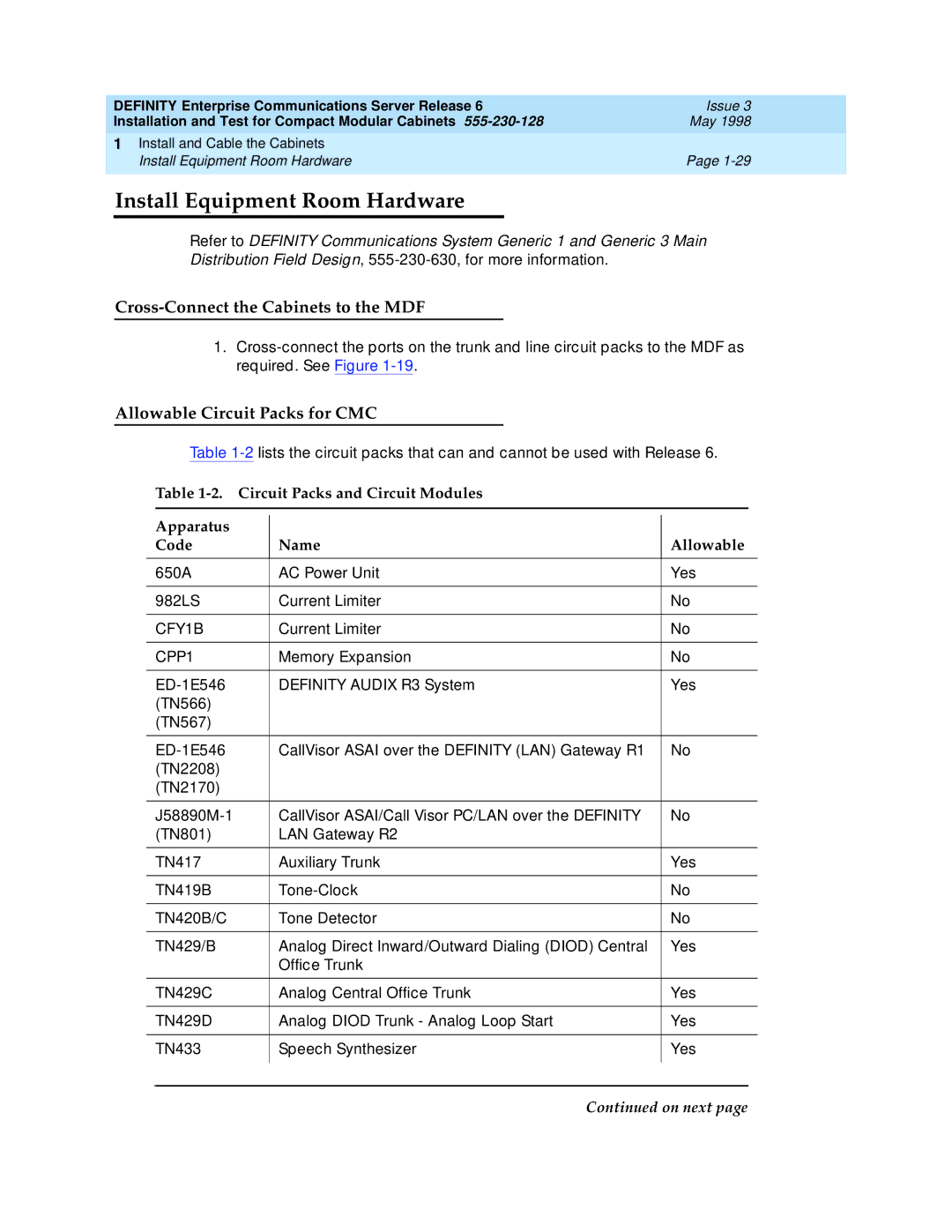
Table
Table
Apparatus |
|
|
| |
Code | Name | Allowable | ||
|
|
|
|
|
650A | AC Power Unit | Yes | ||
|
|
|
|
|
982LS | Current Limiter | No | ||
|
|
|
|
|
CFY1B | Current Limiter | No | ||
|
|
|
|
|
CPP1 | Memory Expansion | No | ||
|
|
|
|
|
DEFINITY AUDIX R3 System | Yes | |||
(TN566) |
|
|
| |
(TN567) |
|
|
| |
|
|
|
|
|
CallVisor ASAI over the DEFINITY (LAN) Gateway R1 | No | |||
(TN2208) |
|
|
| |
(TN2170) |
|
|
| |
|
|
|
|
|
CallVisor ASAI/Call Visor PC/LAN over the DEFINITY | No | |||
(TN801) | LAN Gateway R2 |
|
| |
|
|
|
|
|
TN417 | Auxiliary Trunk | Yes | ||
|
|
|
|
|
TN419B | No | |||
|
|
|
|
|
TN420B/C | Tone Detector | No | ||
|
|
|
|
|
TN429/B | Analog Direct Inward/Outward Dialing (DIOD) Central | Yes | ||
|
| Office Trunk |
|
|
|
|
|
|
|
TN429C | Analog Central Office Trunk | Yes | ||
|
|
|
|
|
TN429D | Analog DIOD Trunk - Analog Loop Start | Yes | ||
|
|
|
|
|
TN433 | Speech Synthesizer | Yes | ||
|
|
|
|
|
|
|
|
|
|
