DEFINITY Enterprise Communications Server Release 6 | Issue 3 |
Installation and Test for Compact Modular Cabinets | May 1998 |
|
|
2Installation Completion and Cable Pinouts
Connector and Cable Diagrams — Pinout Charts |
| Page | ||||||||
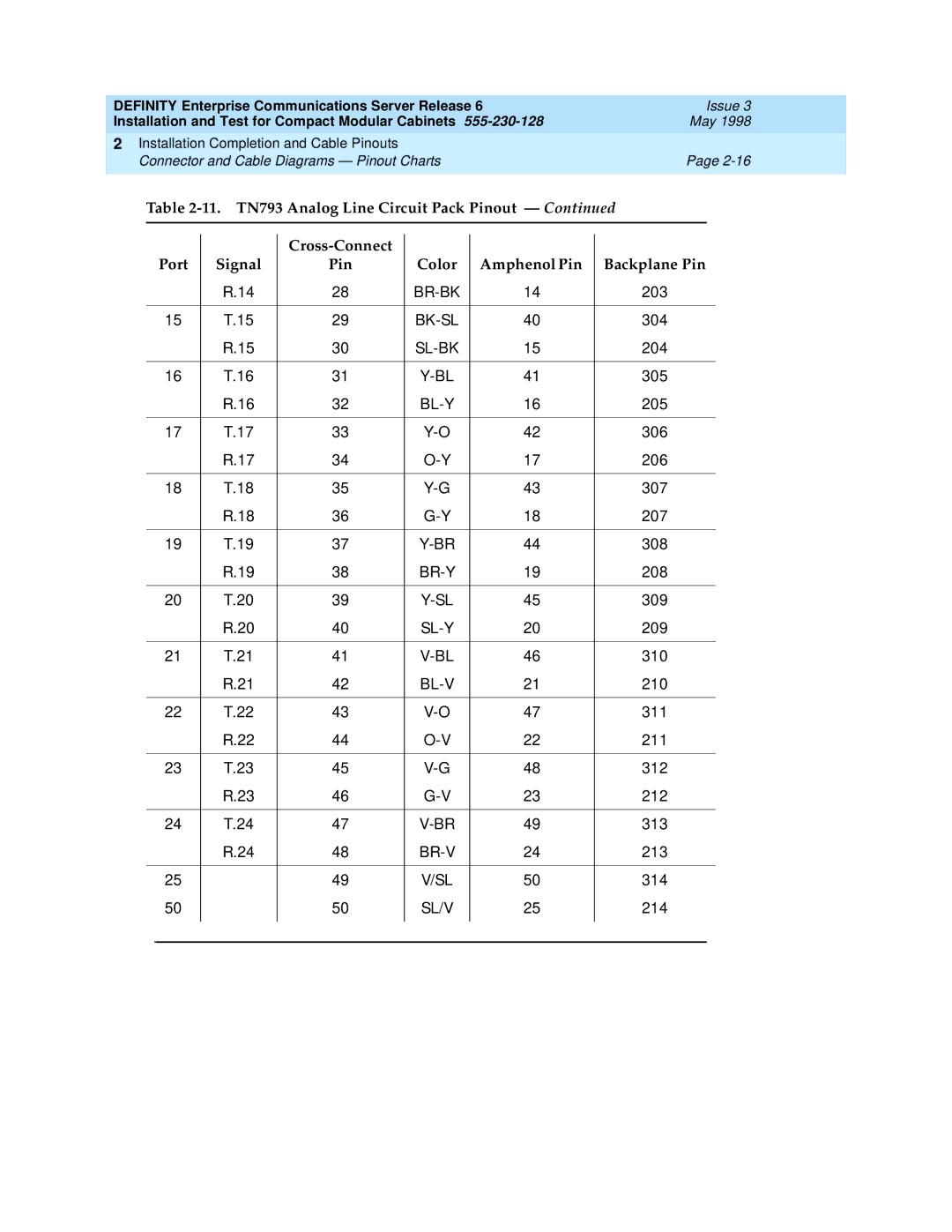
| Table | |||||||||
|
|
|
|
|
|
|
|
|
|
|
|
|
|
|
|
|
|
|
|
| |
|
|
|
|
|
|
|
|
|
| |
|
|
| Port | Signal | Pin | Color | Amphenol Pin | Backplane Pin | ||
|
|
|
| R.14 | 28 | 14 | 203 |
|
| |
|
|
|
|
|
|
|
|
|
| |
15 | T.15 | 29 | 40 | 304 |
|
| ||||
|
|
|
| R.15 | 30 | 15 | 204 |
|
| |
|
|
|
|
|
|
|
|
|
| |
16 | T.16 | 31 | 41 | 305 |
|
| ||||
|
|
|
| R.16 | 32 | 16 | 205 |
|
| |
|
|
|
|
|
|
|
|
|
| |
17 | T.17 | 33 | 42 | 306 |
|
| ||||
|
|
|
| R.17 | 34 | 17 | 206 |
|
| |
|
|
|
|
|
|
|
|
|
| |
18 | T.18 | 35 | 43 | 307 |
|
| ||||
|
|
|
| R.18 | 36 | 18 | 207 |
|
| |
|
|
|
|
|
|
|
|
|
| |
19 | T.19 | 37 | 44 | 308 |
|
| ||||
|
|
|
| R.19 | 38 | 19 | 208 |
|
| |
|
|
|
|
|
|
|
|
|
| |
20 | T.20 | 39 | 45 | 309 |
|
| ||||
|
|
|
| R.20 | 40 | 20 | 209 |
|
| |
|
|
|
|
|
|
|
|
|
| |
21 | T.21 | 41 | 46 | 310 |
|
| ||||
|
|
|
| R.21 | 42 | 21 | 210 |
|
| |
|
|
|
|
|
|
|
|
|
| |
22 | T.22 | 43 | 47 | 311 |
|
| ||||
|
|
|
| R.22 | 44 | 22 | 211 |
|
| |
|
|
|
|
|
|
|
|
|
| |
23 | T.23 | 45 | 48 | 312 |
|
| ||||
|
|
|
| R.23 | 46 | 23 | 212 |
|
| |
|
|
|
|
|
|
|
|
|
| |
24 | T.24 | 47 | 49 | 313 |
|
| ||||
|
|
|
| R.24 | 48 | 24 | 213 |
|
| |
|
|
|
|
|
|
|
|
|
| |
25 |
| 49 | V/SL | 50 | 314 |
|
| |||
50 |
| 50 | SL/V | 25 | 214 |
|
| |||
|
|
|
|
|
|
|
|
|
|
|
|
|
|
|
|
|
|
|
|
|
|