M R V C o m m u n i c a t i o n s , I n c . – I n s t a l l a t i o n M a n u a l
S (for SingleMode)
‘U’ represents operating wavelength.
Instead of U use one of the following: 8 (for 850 nm)
3 (for 1310 nm)
5 (for 1550 nm) ‘W’ represents connector type.
Instead of W use one of the following: C (for SC)
T (for ST)
‘FET’ (Fast ethernet) represents
Instead of V use one of the following:
V designates no
F designates
Instead of S use one of the following:
S (for input to the power supply in the range
Examples
1- TS155/A/M3C/VS means
2- TS155/C2/S3T/F3 :
General Description and explanations
1. Front
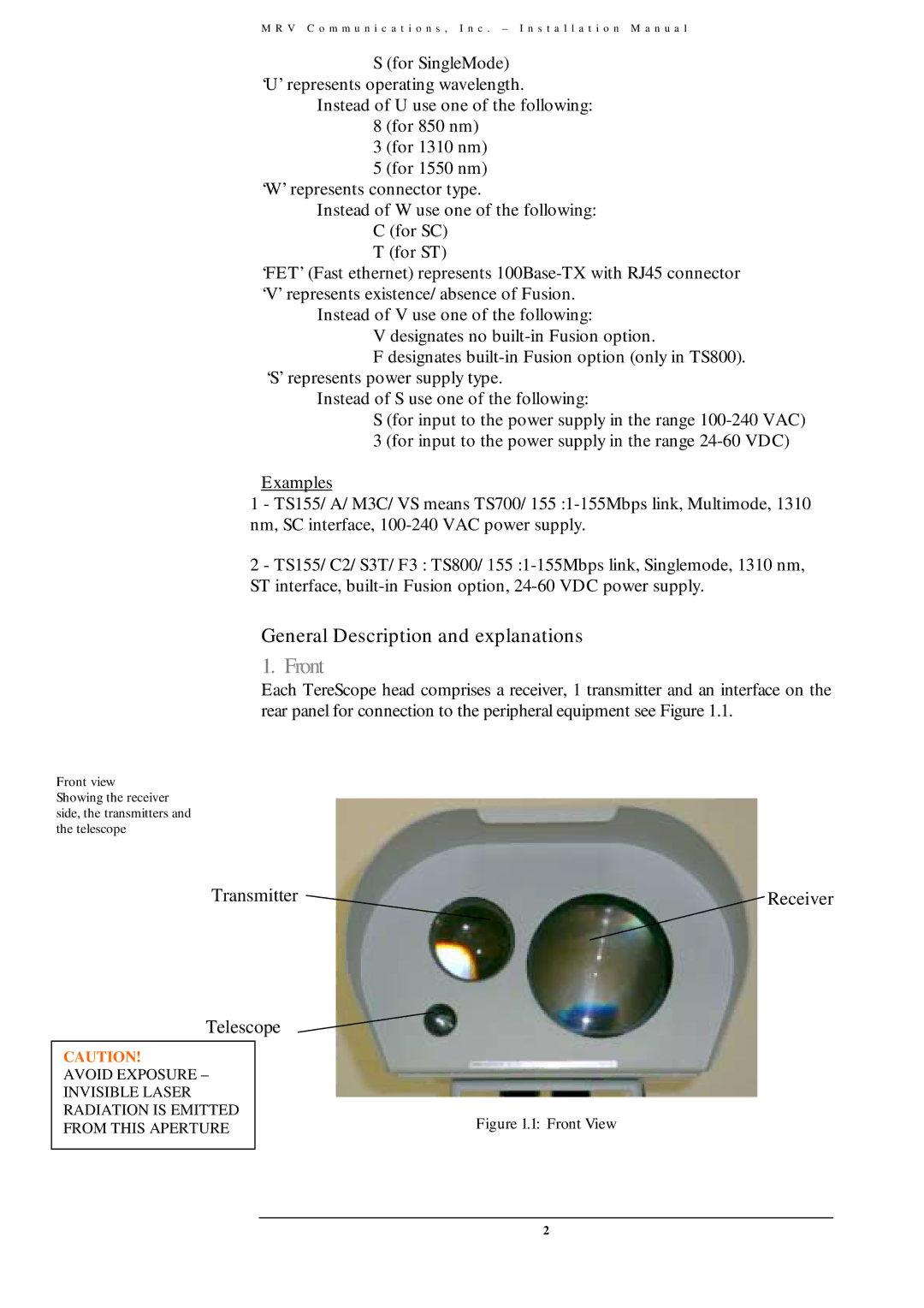
Each TereScope head comprises a receiver, 1 transmitter and an interface on the rear panel for connection to the peripheral equipment see Figure 1.1.
Front view
Showing the receiver side, the transmitters and the telescope
Transmitter | Receiver |
Telescope
CAUTION!
AVOID EXPOSURE – INVISIBLE LASER RADIATION IS EMITTED FROM THIS APERTURE
Figure 1.1: Front View
2