M R V C o m m u n i c a t i o n s , I n c . – I n s t a l l a t i o n M a n u a l
Back Panel Description
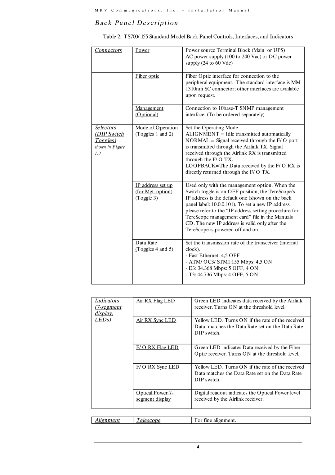
Table 2: TS700/155 Standard Model Back Panel Controls, Interfaces, and Indicators
Connectors | Power | Power source Terminal Block (Main or UPS) |
| |
|
| AC power supply (100 to 240 Vac) or DC power |
| |
|
| supply (24 to 60 Vdc) |
| |
|
|
|
| |
| Fiber optic | Fiber Optic interface for connection to the | ||
|
| peripheral equipment. The standard interface is MM |
| |
|
| 1310nm SC connector; other interfaces are available |
| |
|
| upon request. |
| |
|
|
|
| |
| Management | Connection to | ||
| (Optional) | interface. (To be ordered separately) |
| |
|
|
|
| |
Selectors | Mode of Operation | Set the Operating Mode | ||
(DIP Switch | (Toggles 1 and 2) | ALIGNMENT = Idle transmitted automatically |
| |
Toggles) |
| NORMAL = Signal received through the F/O port |
| |
shown in Figure |
| is transmitted through the Airlink TX. Signal |
| |
1.3 |
| received through the Airlink RX is transmitted |
| |
|
| through the F/O TX. |
| |
|
| LOOPBACK=The Data received by the F/O RX is |
| |
|
| directly returned through the F/O TX. |
| |
|
|
|
| |
| IP address set up | Used only with the management option. When the | ||
| (for Mgt. option) | Switch toggle is on OFF position, the TereScope’s |
| |
| (Toggle 3) | IP address is the default one (shown on the back |
| |
|
| panel label: 10.0.0.101). To set a new IP address |
| |
|
| please refer to the “IP address setting procedure for |
| |
|
| TereScope management card” file in the Manuals |
| |
|
| CD. The new IP address is valid only after the |
| |
|
| TereScope is powered off and on. |
| |
|
|
|
| |
| Data Rate | Set the transmission rate of the transceiver (internal | ||
| (Toggles 4 and 5) | clock). |
| |
|
| - Fast Ethernet: 4,5 OFF |
| |
|
| - ATM/OC3/STM1:155 Mbps: 4,5 ON |
| |
|
| - E3: 34.368 Mbps: 5 OFF, 4 ON |
| |
|
| - T3: 44.736 Mbps: 4 OFF, 5 ON |
| |
|
|
|
|
|
|
|
|
|
|
Indicators | Air RX Flag LED |
| Green LED indicates data received by the Airlink | |
|
| receiver. Turns ON at the threshold level. | ||
display, |
|
|
|
|
LEDs) | Air RX Sync LED |
| Yellow LED. Turns ON if the rate of the received | |
|
|
| Data matches the Data Rate set on the Data Rate | |
|
|
| DIP switch. | |
|
|
|
|
|
| F/O RX Flag LED |
| Green LED indicates Data received by the Fiber | |
|
|
| Optic receiver. Turns ON at the threshold level. | |
|
|
|
|
|
| F/O RX Sync LED |
| Yellow LED. Turns ON if the rate of the received | |
|
|
| Data matches the Data Rate set on the Data Rate | |
|
|
| DIP switch. | |
|
|
|
|
|
| Optical Power 7- |
| Digital readout indicates the Optical Power level | |
| segment display |
| received by the Airlink receiver. | |
|
|
|
|
|
Alignment
Telescope
For fine alignment.
4