M R V C o m m u n i c a t i o n s , I n c . – I n s t a l l a t i o n M a n u a l
Note
The Tower Mount and the Clamping Plate are not provided with the equipment and should be supplied by the installer.
3- Attachment of the Transceiver (TereScope Head)
After securely attaching
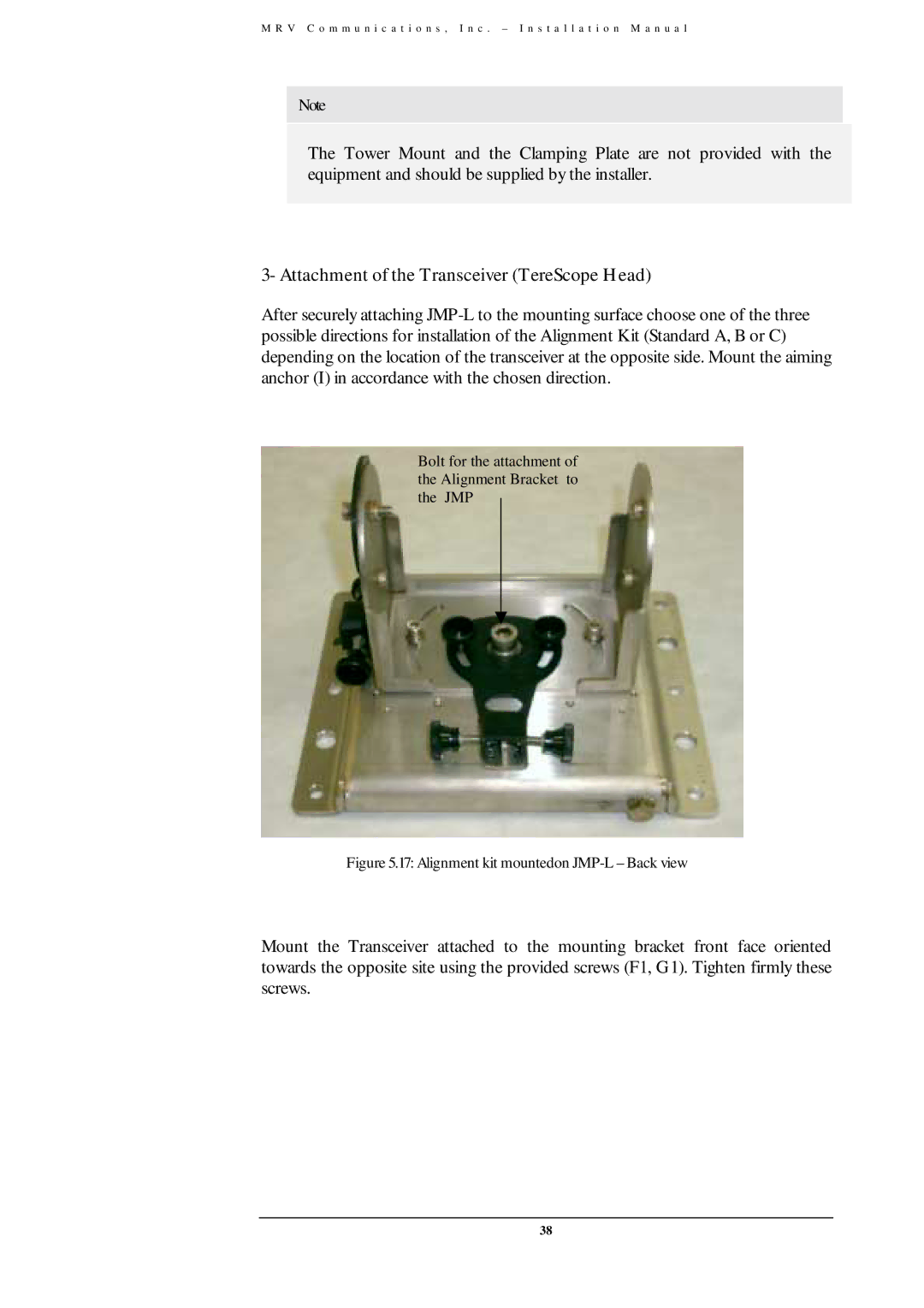
Bolt for the attachment of the Alignment Bracket to the JMP
Figure 5.17: Alignment kit mountedon JMP-L – Back view
Mount the Transceiver attached to the mounting bracket front face oriented towards the opposite site using the provided screws (F1, G1). Tighten firmly these screws.
38