Manuals
/
Brands
/
Computer Equipment
/
Network Card
/
MRV Communications
/
Computer Equipment
/
Network Card
MRV Communications
TS700/100, TS700/155, TS700/G, TS800/155
- page 55
1
55
77
77
Download
77 pages, 1.13 Mb
MRV Communications, Inc. – Insta llation Manual
45
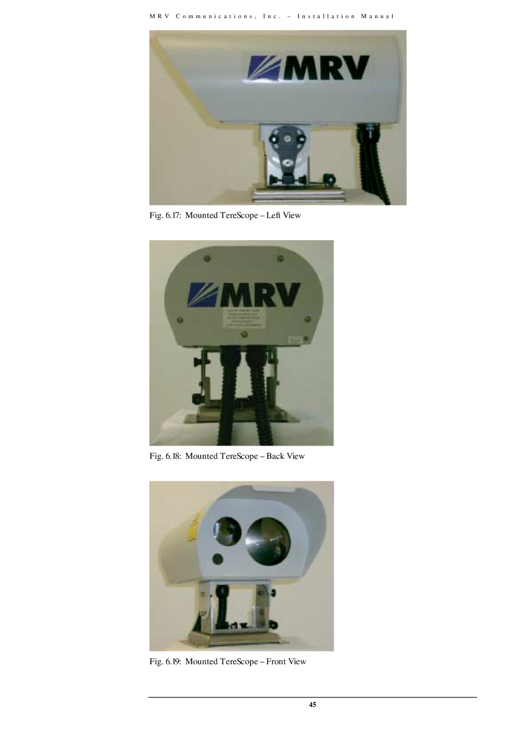
Fig. 6.17: Mounted TereScope – Left View
Fig. 6.18: Mounted TereScope – Back View
Fig. 6.19: Mounted TereScope – Front View
Contents
Main
TereScope700 and TereScope800
User Manual
Wireless Optical Communication Links
Models TS700/100, TS700/155, TS700/G, TS800/155
User Manual
February 2006
Table of Contents
Page
Standards
Standards Compliance
FCC Notice
CE Mark
Other Standards
MRV
Laser Safety Certification
Disclaimer
Trademarks
About this User Manual
Audience
Qualifications
Training
Experience
Safety Requirements
Before Installing
Before Powering On
Servicing
Introduction
CAREFULLY READ THE ENTIRE MANUAL BEFORE INSTALLING
A
!!
!
The Product
Models Models Part Number Description
General Description and explanations
1. Front
MRV
2. Back
A. TS700/155 (Standard Model)
Indicators (7-segment display, LEDs)
Connectors
Power Power source Terminal Block (Main or UPS)
Selectors (DIP Switch
B. TS800/155 Standard Model
Note:
Selectors (DIP Switch DS1 Toggles)
Selectors (DIP Switch DS2 Toggles)
Indicators (7-segment display and LEDs)
C. TS800/155-F (Standard Model including Fusion option)
Page
Fusion
D. TS700/100 - Fast-Ethernet System
Page
MRV
Connectors
Indicators (7-segment display, LEDs),Dry Contact Alarms
Selectors (DIP Switch
Monitoring and Management options
Typical Connection
IT IS A CROSS CONNECTION: TX $ $$
$RX AND RX $ $$
$ TX
Site Survey
Line of Sight
Orientation
Location & Range
&&
Page
Mounting Environment & Stability
Page
Transmitting through a Window
Page
Infrastructure
!!
Power
Data/Signal Cabling
!
HANDLE THE FIBERS VERY CAREFULLY.
( !
Bench Test
Page
Compatibility
Test equipment
Setup
Bench test
IR link
IR link
UWIN RX
TS TS
IR link
TX
Page
Installation
&&
Accessories
&
Part Description Part Description
AIMING HEAD ADJUSTMENT AND LOCKS:
The Installer Tool Kit (JITK-L)
Mounting
Page
&&
Special Mounting
&
!!
!
Page
Aiming Procedure
Powering on the TereScope
Transceiver Alignment
Page
Page
(
Link Operating Test
IT IS A CROSS CONNECTION: TX $RX AND RX $ TX
Installation Log
Before Closing the Rear Door
Installation Completion
Page
Maintenance
(
Periodic Visits
Product Specifications )high speed Light (700/155TS
A
PPENDIX A
TS700/100 (Fast-Ethernet Light)
TS800/155 (high speed Light)
TS700/G (Giga-Light)
Digital Readout vs. Distance
APPENDIX B
Unpacking Instructions for TereScope
APPENDIX C
Tool Kit, Equipment, and Materials
APPENDIX D
6.
Page
TereScopes Bench Test Procedure
APPENDIX E
Page
Page
Page
Effect of Wind on Terescopes
APPENDIX F
Appendix G
Page
Page
APPENDIX H
Page
Page
Page
APPENDIX I