M R V C o m m u n i c a t i o n s , I n c . – I n s t a l l a t i o n M a n u a l
Link Operating Test
Set back the Mode Select
At both sites, connect with fiberoptic or STP cables coming from the peripheral equipment to the fiberoptic or copper port of the transceiver.
IT IS A CROSS CONNECTION:
TX ∃RX AND RX ∃ TX
The F/O RX Flag and Sync. (Electrical flag and Rx on TS700/100) indicators should turn ON as soon as the peripheral equipment is powered ON.
A BER test is recommended. In case this is not possible at least check with the customer/user the performance of the whole link (see the chapter Bench Test).
Installation Log
Write down all the information about the installation (including digital readout and the setup of the transceivers) in an installation log. This information is a valuable reference for future maintenance or troubleshooting visits.
An example of an installation form is shown in Appendix H.
Before Closing the Rear Door
1.Ensure that the Power Supply Cover is fastened in place.
2.All cables are properly held in position.
Visual Inspection
Visually check that all parts and cables are connected.
Closing the rear door
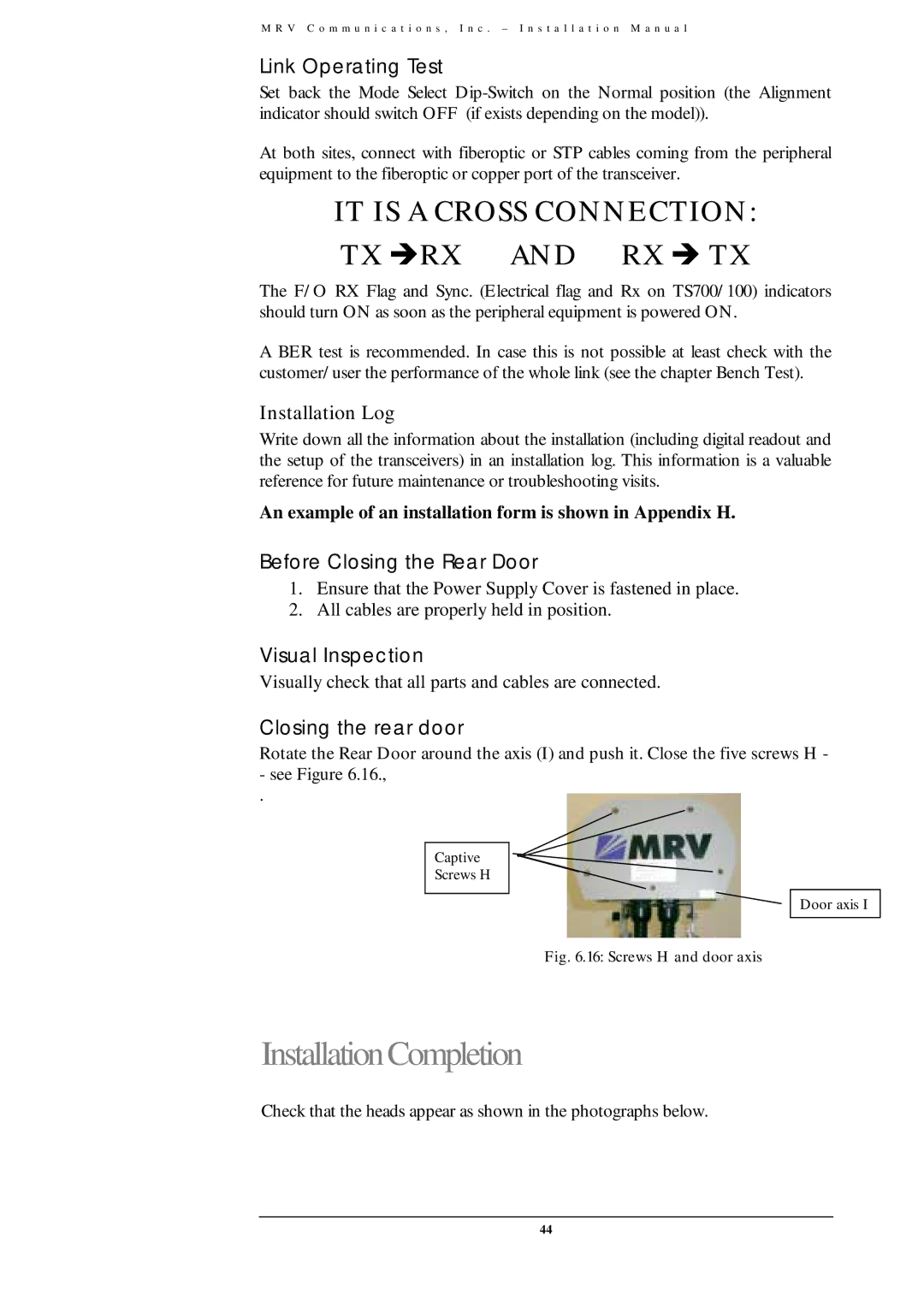
Rotate the Rear Door around the axis (I) and push it. Close the five screws H -
-see Figure 6.16.,
.
Captive
Screws H
Door axis I
Fig. 6.16: Screws H and door axis
InstallationCompletion
Check that the heads appear as shown in the photographs below.
44