M R V C o m m u n i c a t i o n s , I n c . – I n s t a l l a t i o n M a n u a l
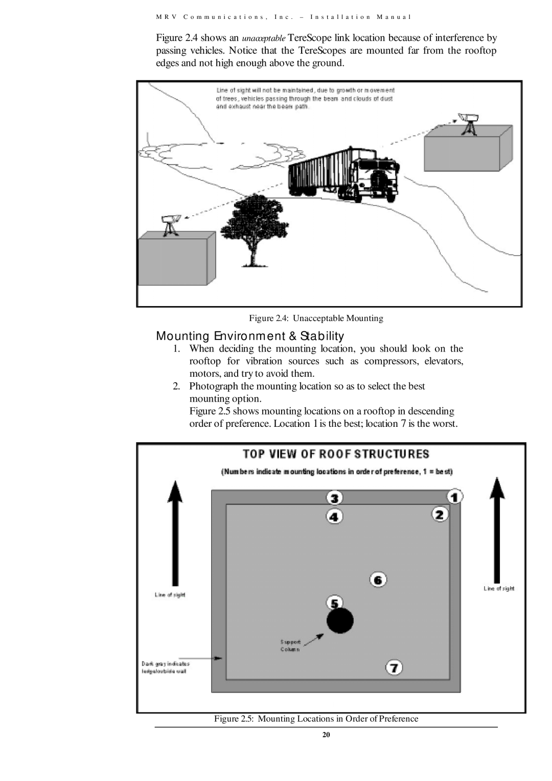
Figure 2.4 shows an unacceptable TereScope link location because of interference by passing vehicles. Notice that the TereScopes are mounted far from the rooftop edges and not high enough above the ground.
Figure 2.4: Unacceptable Mounting
Mounting Environment & Stability
1.When deciding the mounting location, you should look on the rooftop for vibration sources such as compressors, elevators, motors, and try to avoid them.
2.Photograph the mounting location so as to select the best mounting option.
Figure 2.5 shows mounting locations on a rooftop in descending order of preference. Location 1 is the best; location 7 is the worst.
Figure 2.5: Mounting Locations in Order of Preference
20