M R V C o m m u n i c a t i o n s , I n c . – I n s t a l l a t i o n M a n u a l
APPENDIXI | Power over Ethernet |
The Power-over-Ethernet (PoE) option is available only for Low Voltage TereScope model 700/100. PoE eliminates a separate DC power supply cable at each Access Point (AP) location, i.e., it allows for a single Ethernet cable providing both data and power to be run to each AP instead of two separate cables, one for power and the other for data. There are two types of PoE connections. One type utilizes all 8 wires of the Ethernet cable. The wires that are connected to pins 1, 2, 3, and 6 carry both power as well as data. The other type utilizes the four wires that are connected to pins 1, 2, 3, and 6 for carrying data, and the four other wires that connect to pins 4, 5, 7, and 8 for carrying power. Pin 4 is shorted to pin 5 and these are connected to the
(+)terminal of the power supply. Pin 7 is shorted to pin 8 and these are connected to the (-) terminal of the power supply. Both are floating isolated voltage as is usual for a -48V Telecom supply. TereScope model 700/100 with PoE option supports this second option only (as required per IEEE 802.3af standard) so proper connection to this pins should be provided.
The TereScope model 700/100 can be connected by any of the following three methods:
1.TereScope model 700/100 with PoE option is connected directly to PoE-enabledequipment –The only needed part is a straight (non-cross) Category 5 jr 5e cable, which will also supply power to the AP.
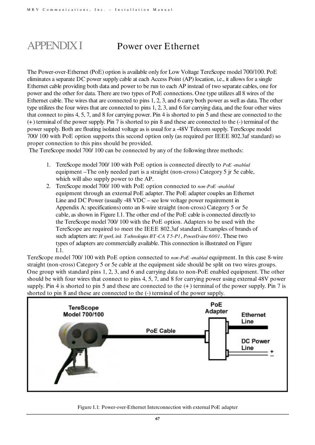
2.TereScope model 700/100 with PoE option connected to non-PoE-enabledequipment through an external PoE adapter. The PoE adapter couples an Ethernet Line and DC Power (usually -48 VDC – see low voltage power requirement in Appendix A: specifications) onto an 8-wire straight (non-cross) Category 5 or 5e cable, as shown in Figure I.1. The other end of the PoE cable is connected directly to the TereScope model 700/100 with the PoE option. Adapters to be used with the TereScope are required to meet the IEEE 802.3af standard. Examples of brands of such adapters are: HyperLink Technologies BT-CAT5-P1, PowerDsine 6001. These two
types of adapters are commercially available. This connection is illustrated on Figure I.1.
TereScope model 700/100 with PoE option connected to non-PoE-enabledequipment. In this case 8-wire straight (non-cross) Category 5 or 5e cable at the equipment side should be split on two wires groups. One group with standard pins 1, 2, 3, and 6 and carrying data to non-PoE enabled equipment. The other should be with four wires that connect to pins 4, 5, 7, and 8 for carrying power using external 48V power supply. Pin 4 is shorted to pin 5 and these are connected to the (+) terminal of the power supply. Pin 7 is shorted to pin 8 and these are connected to the (-) terminal of the power supply.
Figure I.1: Power-over-Ethernet Interconnection with external PoE adapter