M R V C o m m u n i c a t i o n s , I n c . – I n s t a l l a t i o n M a n u a l
allows for testing each transmitter separately. By rotating the devices 45 degrees, the next pair of transmitters is tested. Hence, testing all 8 transmitters in the link pair requires only 4 rotations.
In the 8” setup, the two devices are not centrally aligned; instead, only one corner of each device faces the opposite device. This allows for testing each transmitter separately. By rotating the devices 45 degrees, the next pair of transmitters is tested. Hence, testing all
6 transmitters in the link pair requires only 3 rotations. With opaque masking tape, cover all transmitters that are not under test.
Table 1: Bench Test Information for TS Products
Product name | Opt. Power M. | Potential for | |
value | Interference | ||
| |||
TSxxxx | 1100 | Low | |
TSxxx/ETH | 1200 | Med | |
TSxxx/E1 | 1200 | High | |
TSxxxx/ST | 1200 | Med | |
TS2000/XXX | 1100 | High | |
TS4000/XXX | 1200 | High | |
TSx00/XXX | 1000 | High |
Figure E.1: Bench Test setup for 4”/Light TS models.
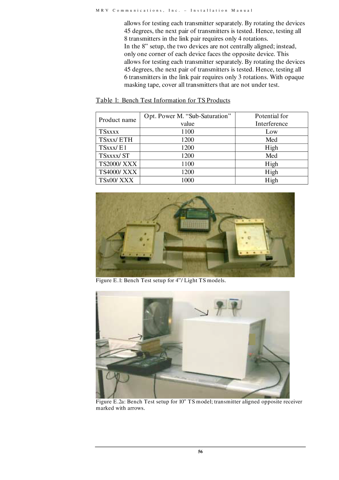
Figure E.2a: Bench Test setup for 10” TS model; transmitter aligned opposite receiver marked with arrows.
56