M R V C o m m u n i c a t i o n s , I n c . – I n s t a l l a t i o n M a n u a l
(1)In case such situations cannot be avoided, special mounting accessories and techniques must be designed and considered (see section Particular Figure Cases\Techniques page 37)
Prefer | Avoid | Pay attention to |
|
Concrete Parapet | Old constructions | Colored windows |
|
Structural wall or | Soft material (asphalt, etc.) | Double glazing |
|
column | The proximity of power |
| |
| Wooden and metal | radio antennas |
|
| structures |
|
|
&the units indoors as long as all the required conditions previously described are met and the customer/building owner allows it. However, when windows are present in the beam path, the attenuating factor of the glass must be considered regarding the distance and the required fade margin.
2.Referring to the data in Appendix A: Product Specifications, set and record the distance between the two TereScopes of the link. (You can use any of the following equipment to determine the distance: rangefinder laser binoculars, GPS receiver, maps, etc.)
3.Noting that two TereScope units are required per link, record the quantity of each model of the TereScope required.
4.Record the bearing to the opposite site by compass.
5.Record the number of links to be installed at the site.
6.Note whether additional sheltering is needed for the TereScope, for e.g., against strong winds (120km/h or more)For reasons of convenience, it is always preferable to install
CONSULT FACTORY IN CASE OF DOUBT !
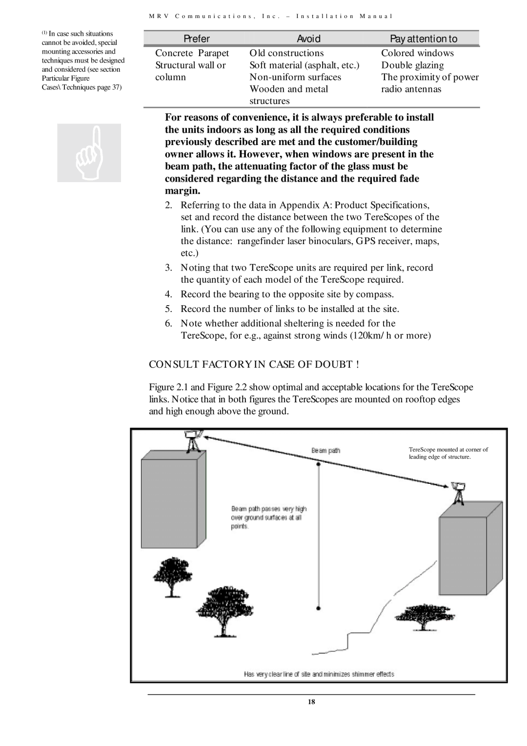
Figure 2.1 and Figure 2.2 show optimal and acceptable locations for the TereScope links. Notice that in both figures the TereScopes are mounted on rooftop edges and high enough above the ground.
TereScope mounted at corner of leading edge of structure.
18
