M R V C o m m u n i c a t i o n s , I n c . – I n s t a l l a t i o n M a n u a l
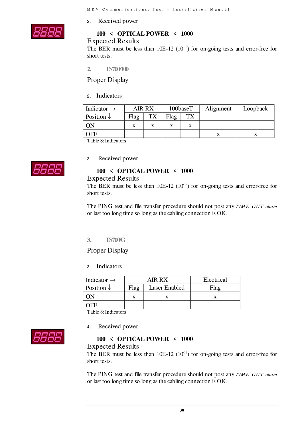
2.Received power
100 < OPTICAL POWER < 1000
Expected Results
The BER must be less than
2.TS700/100
Proper Display
2. Indicators |
|
|
|
|
|
| |
|
|
|
|
|
|
|
|
Indicator → |
| AIR RX | 100baseT | Alignment | Loopback | ||
Position ↓ |
| Flag | TX | Flag | TX |
|
|
ON |
| x | x | x | x |
|
|
OFF |
|
|
|
|
| x | x |
Table 8: Indicators |
|
|
|
|
|
|
|
3.Received power
100 < OPTICAL POWER < 1000
Expected Results
The BER must be less than
The PING test and file transfer procedure should not post any TIME OUT alarm or last too long time so long as the cabling connection is OK.
3.TS700/G
Proper Display
3. Indicators |
|
|
| |
|
|
|
|
|
Indicator → |
|
| AIR RX | Electrical |
Position ↓ |
| Flag | Laser Enabled | Flag |
ON |
| x | x | x |
OFF |
|
|
|
|
Table 8: Indicators |
|
|
|
|
4.Received power
100 < OPTICAL POWER < 1000
Expected Results
The BER must be less than
The PING test and file transfer procedure should not post any TIME OUT alarm or last too long time so long as the cabling connection is OK.
30
