M R V C o m m u n i c a t i o n s , I n c . – I n s t a l l a t i o n M a n u a l
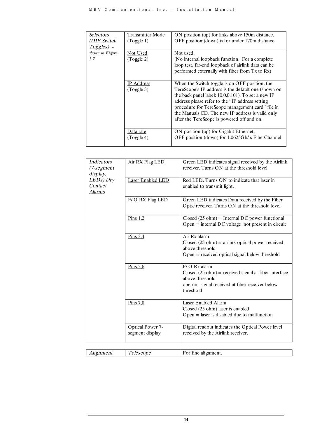
Selectors | Transmitter Mode | ON position (up) for links above 150m distance. |
| |
(DIP Switch | (Toggle 1) | OFF position (down) is for under 170m distance |
| |
Toggles) |
|
|
|
|
shown in Figure | Not Used | Not used. |
| |
1.7 | (Toggle 2) | (No internal loopback function. For a complete |
| |
|
| loop test, |
| |
|
| performed externally with fiber from Tx to Rx) |
| |
|
|
|
| |
| IP Address | When the Switch toggle is on OFF position, the | ||
| (Toggle 3) | TereScope’s IP address is the default one (shown on |
| |
|
| the back panel label: 10.0.0.101). To set a new IP |
| |
|
| address please refer to the “IP address setting |
| |
|
| procedure for TereScope management card” file in |
| |
|
| the Manuals CD. The new IP address is valid only |
| |
|
| after the TereScope is powered off and on. |
| |
|
|
|
| |
| Data rate | ON position (up) for Gigabit Ethernet, | ||
| (Toggle 4) | OFF position (down) for 1.0625Gb/s FiberChannel |
| |
|
|
|
|
|
|
|
|
|
|
Indicators | Air RX Flag LED |
| Green LED indicates signal received by the Airlink | |
|
| receiver. Turns ON at the threshold level. | ||
display, |
|
|
|
|
LEDs),Dry | Laser Enabled LED |
| Red LED. Turns ON to indicate that laser in | |
Contact |
|
| enabled to transmit light. | |
Alarms |
|
|
|
|
| F/O RX Flag LED |
| Green LED indicates Data received by the Fiber | |
|
|
| Optic receiver. Turns ON at the threshold level. | |
|
|
|
|
|
| Pins 1,2 |
| Closed (25 ohm) = Internal DC power functional | |
|
|
| Open = internal DC voltage not present in circuit | |
|
|
|
|
|
| Pins 3,4 |
| Air Rx alarm | |
|
|
| Closed (25 ohm) = airlink optical power received | |
|
|
| above threshold | |
|
|
| Open = received optical signal below threshold | |
|
|
|
|
|
| Pins 5,6 |
| F/O Rx alarm | |
|
|
| Closed (25 ohm) = received signal at fiber interface | |
|
|
| above threshold | |
|
|
| open = signal received at fiber receiver below | |
|
|
| threshold | |
|
|
|
|
|
| Pins 7,8 |
| Laser Enabled Alarm | |
|
|
| Closed (25 ohm) laser is enabled | |
|
|
| Open = laser is disabled due to malfunction | |
|
|
|
|
|
| Optical Power 7- |
| Digital readout indicates the Optical Power level | |
| segment display |
| received by the Airlink receiver. | |
|
|
|
|
|
Alignment
Telescope
For fine alignment.
14