M R V C o m m u n i c a t i o n s , I n c . – I n s t a l l a t i o n M a n u a l
APPENDIXB | Digital Readout vs. Distance |
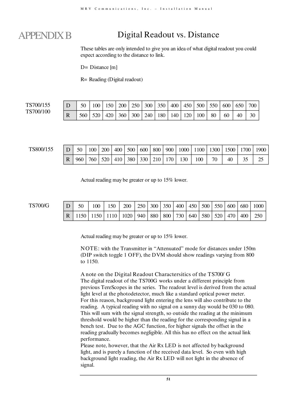
TS700/155
TS700/100
TS800/155
These tables are only intended to give you an idea of what digital readout you could expect according to the distance to link.
D= Distance [m]
R= Reading (Digital readout)
D | 50 | 100 | 150 | 200 | 250 | 300 | 350 | 400 | 450 | 500 | 550 | 600 | 650 | 700 |
R | 560 | 520 | 420 | 360 | 300 | 240 | 180 | 140 | 120 | 100 | 80 | 60 | 40 | 30 |
|
|
|
|
|
|
|
|
|
|
|
|
|
|
|
D | 50 | 100 | 200 | 400 | 500 | 600 | 800 | 900 | 1000 | 1100 | 1300 | 1500 | 1700 | 1900 |
R | 960 | 760 | 520 | 410 | 380 | 330 | 210 | 170 | 130 | 100 | 70 | 40 | 35 | 25 |
|
|
|
|
|
|
|
|
|
|
|
|
|
|
|
Actual reading may be greater or up to 15% lower.
TS700/G | D | 50 | 100 | 150 | 200 | 250 | 300 | 350 | 400 | 450 | 500 | 550 | 600 | 680 | 1000 |
| R | 1150 | 1150 | 1110 | 1020 | 940 | 880 | 800 | 730 | 640 | 580 | 520 | 470 | 400 | 250 |
|
|
|
|
|
|
|
|
|
|
|
|
|
|
|
|
Actual reading may be greater or up to 15% lower.
NOTE: with the Transmitter in “Attenuated” mode for distances under 150m (DIP switch toggle 1 OFF), the DVM should show readings varying from 800 to 1150.
A note on the Digital Readout Charactersitics of the TS700/G
The digital readout of the TS700G works under a different principle from previous TereScopes in the series. The readout level is derived from the actual light level at the photodetector, much like a standard optical power meter. For this reason, background light entering the lens will also contribute to the reading. A typical reading with no signal on a sunny day would be 030 to 080. This will sum with the signal strength, so outside the reading at the minimum threshold would be higher than the reading for the corresponding signal in a bench test. Due to the AGC function, for higher signals the offset in the reading gradually becomes negligible. All this has no effect on the actual link performance.
Please note, however, that the Air Rx LED is not affected by background light, and is purely a function of the received data level. So even with high background light reading, the Air Rx LED will not light in the absence of signal.
51