M R V C o m m u n i c a t i o n s , I n c . – I n s t a l l a t i o n M a n u a l
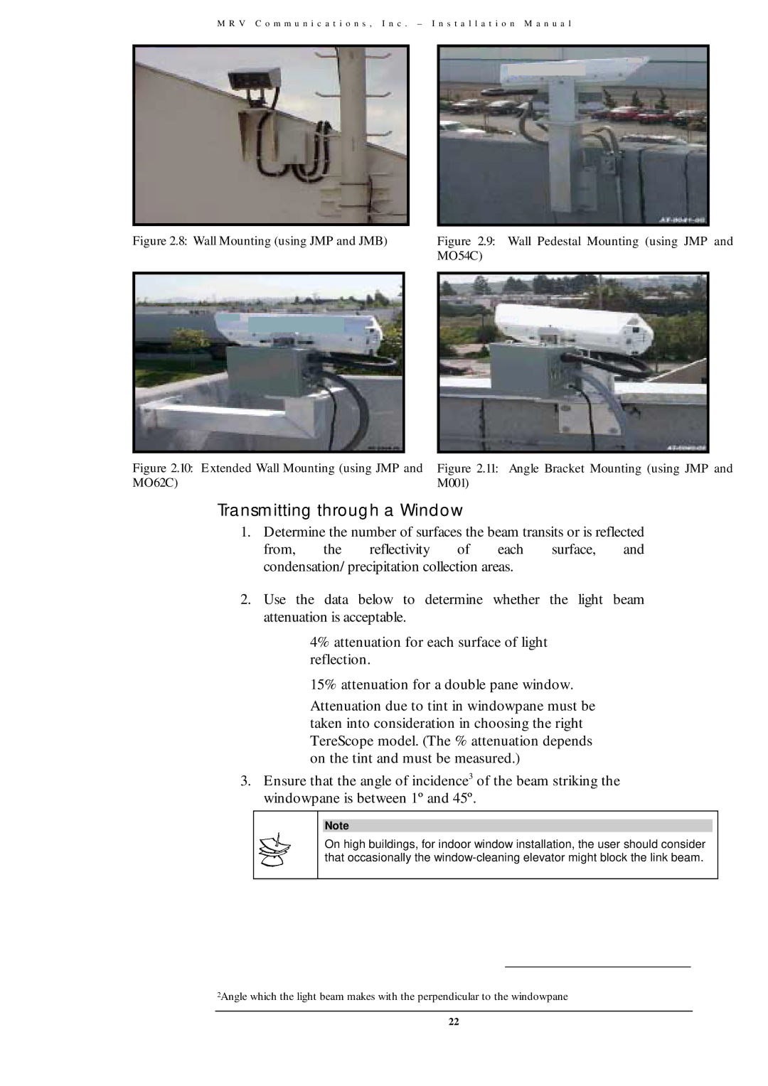
Figure 2.8: Wall Mounting (using JMP and JMB) |
| Figure 2.9: Wall Pedestal Mounting (using JMP and | |||||||||||
|
|
|
|
|
| MO54C) | |||||||
|
|
|
|
|
|
|
|
|
|
|
|
|
|
|
|
|
|
|
|
|
|
|
|
|
|
|
|
|
|
|
|
|
|
|
|
|
|
|
|
|
|
|
|
|
|
|
|
|
|
|
|
|
|
|
|
|
|
|
|
|
|
|
|
|
|
|
|
|
|
Figure 2.10: Extended Wall Mounting (using JMP and | Figure 2.11: Angle Bracket Mounting (using JMP and |
MO62C) | M001) |
Transmitting through a Window
1.Determine the number of surfaces the beam transits or is reflected from, the reflectivity of each surface, and condensation/precipitation collection areas.
2.Use the data below to determine whether the light beam attenuation is acceptable.
4% attenuation for each surface of light reflection.
15% attenuation for a double pane window.
Attenuation due to tint in windowpane must be taken into consideration in choosing the right TereScope model. (The % attenuation depends on the tint and must be measured.)
3.Ensure that the angle of incidence3 of the beam striking the windowpane is between 1º and 45º.
Note
On high buildings, for indoor window installation, the user should consider that occasionally the
2Angle which the light beam makes with the perpendicular to the windowpane
22