M R V C o m m u n i c a t i o n s , I n c . – I n s t a l l a t i o n M a n u a l
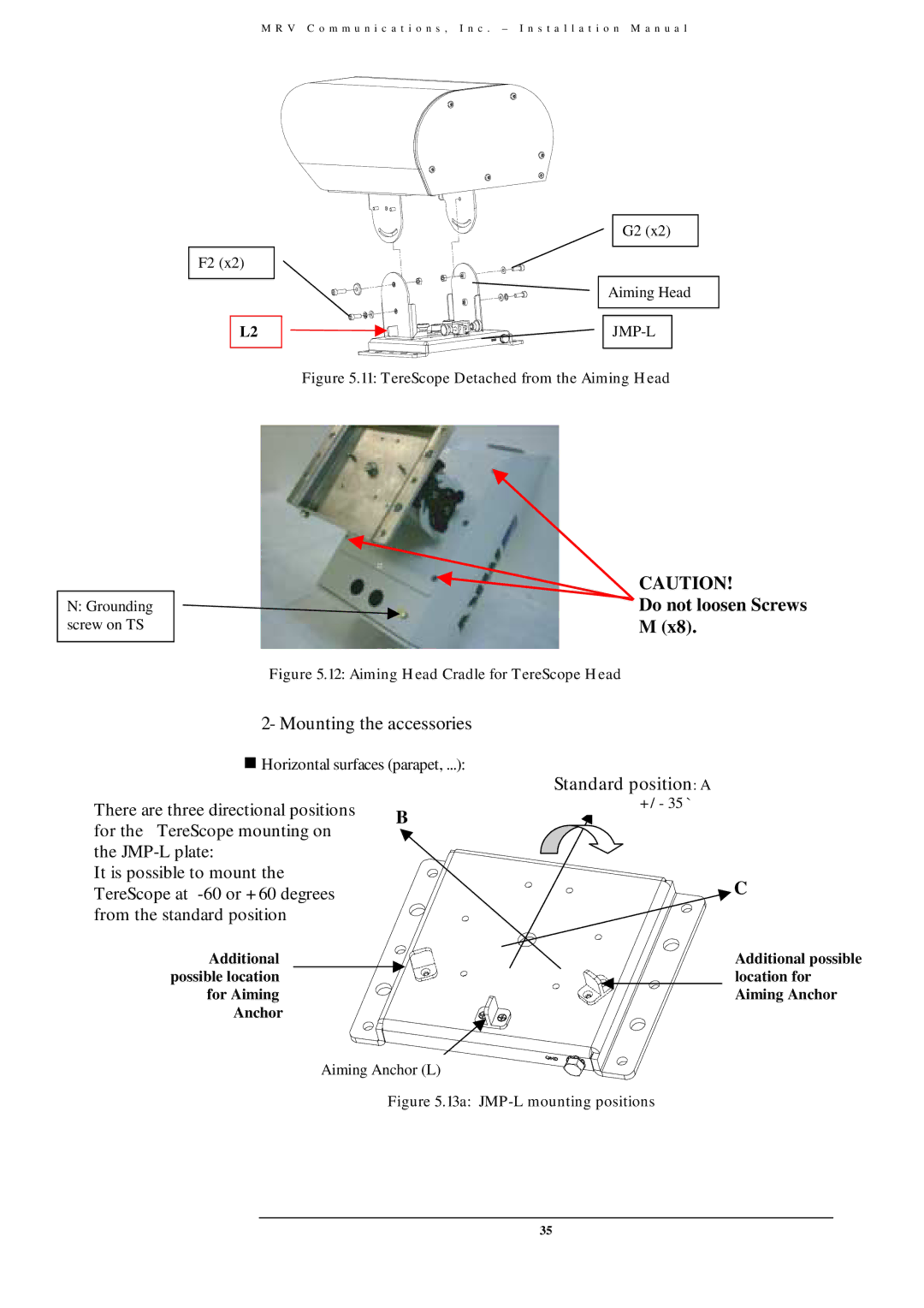
N:Grounding screw on TS
G2 (x2)
F2 (x2)
Aiming Head
L2 ![]()
![]()
![]()
![]()
![]()
Figure 5.11: TereScope Detached from the Aiming Head
CAUTION!
Do not loosen Screws
M (x8).
Figure 5.12: Aiming Head Cradle for TereScope Head
2- Mounting the accessories
)Horizontal surfaces (parapet, ...):
There are three directional positions | B | |
for the TereScope mounting on | ||
| ||
the |
| |
It is possible to mount the |
| |
TereScope at |
| |
from the standard position |
|
Additional possible location for Aiming Anchor
Standard position: A
+/- 35 `
C
Additional possible location for Aiming Anchor
Aiming Anchor (L)
Figure 5.13a: JMP-L mounting positions
35