Users Guide
Page
Table of Contents
Site Preparation
Users Guide
Installation
Calibration
Operation
Programming
Users Guide
Viii Users Guide
Troubleshooting
Appendix a Programming Worksheets
Revision Record
Radio Frequency Interference Statements
Federal Communications Commission FCC
Canadian Department of Communications
Voluntary Control Council For Interference Vcci
Mark Applicability
Scale Regulatory
Declaration of Conformity
This Directive is not applicable to NCR 7870-1000 or NCR
Scale Identification Label
NCR Corporation
Laser Safety
Laser Safety Label
Country Language Specific IEC Class 1 Laser Labels
Laser Power
Laser Module Label
Microwatts
Milliwatts
Introduction
About the NCR 7870 Scanner/Scale
Models
Common Features
Reading the Product Number
7870-1000-9090
7870-2000-9090
7870-3000-9090
7870-4000-9090
General Features and Functions
Bar Code Recognition
Decode Features
Mode 1 Inquiry Mode
Bi-Optic Scanning
Pacesetter Plus
Mode 2 Real-Time Mode
Mode 3 Operations Mode
Displays
NCR 7825 Remote Display
Integrated Display
Power Supply
Interface Types
Laser Scanner
No Display
Programming
Sizes section in Site Preparation
Scale Certifications
Scanner Power Requirements
Soft Power Down
Scan Zone
Top Plates and Scan Windows
Top Plates
Slot Scanner Window
Side Scanner Window
Scale Features and Functions
Scale Functions and Features
Reset / Scale Zero
Load Cell
Kits
Kit Name Kit Type Available for
Kit Name Kit Type Available for
Kit Name Kit Type Available for
Chapter
Kit Name Kit Type Available for
Kit Name Kit Type Available for
Features, Functions, and Kits
Site Preparation
Getting Started
Site Preparation
About Site Preparation
Site Preparation
Customer Responsibilities
Environmental Requirements
Operating Range
Extreme Operating Range
Storage Range
Transit Range
Checkstand Power and Wiring Considerations
Power Considerations
Power Applications
Power Transients Protection
Wiring Considerations
Canadian, and Japanese Checkstand Wiring
European Checkstand Wiring
220Vac Store
International Checkstand Wiring
Wiring Instructions
Running Feeder Lines from Main Service Panel
Circuit a
Circuit B
Circuit C
Checkstand Considerations
Ventilation Requirements
Service Clearance
Display Clearance
Item Diverter
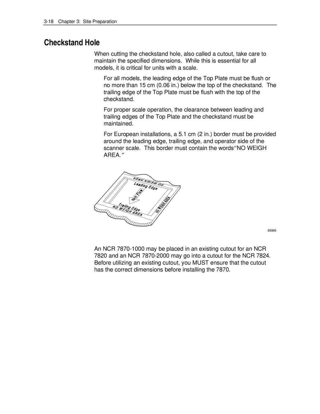
Checkstand Hole
Checkstand Hole Models 1000
NCR 7870-1000 Scanner
Checkstand Hole Models 3000, 4000
NCR 7870 3000 Scanner
DC Power Cable Power Supply to
Cable Lengths and Hole Sizes
Cable Hole Diameters
Minimum Hole Diameter 1.52 cm 0.60
AC Power Cords Outlet to Power Supply
Remote Display Cables
Minimum Hole Diameter 3.18 cm 1.25
Minimum Hole Diameter 1.90 cm 0.75
Interface Cables NCR Host Terminals
Host Interface Cable Corporate Part Length Terminal Number
Interface Cables NCR Host Terminals
Interface Cables Casio Host Terminals
Interface Cables Data Checker Host Terminals
Interface Cables Epson Host Terminals
Interface Cables Gilbarco Host Terminals
Interface Cables IBM Host Terminals
Interface Cables ICL Host Terminals
Interface Cables Microbilt Host Terminals
Interface Cables NEC Host Terminals
Interface Cables Sasi Host Terminals
NCR 7870 Dimensions
NCR 7870 1000 Dimensions
NCR 7870 2000 Dimensions
NCR 7870-1000 & 2000 Models
NCR 7870 3000 Dimensions
NCR 7870-3000 Model
NCR 7870 4000 & 4500 Dimensions
NCR 7870-4000 & 4500 Models
Reporting a Damaged Unit
What’s in the Box
Cable Verification
Checkstand Verification
Installing Unit in Checkstand
Install Cables
Instructions
Single Cable Set-Up
Dual Cable Set-Up
Datachecker or RS-232 Cable Set-Up
Tower Subplate Assembly Cover/Lift Strap
If the NCR 7870 Does Not Pass Level O Diagnostics
Determining if the Unit is Operational
NCR 7870-1000 and 3000 Scanners
NCR 7875-2000, 4000, and 4500 Scanner/Scales
Checkout Reading Operation
Determining Communications Protocol
Scale Address for IBM
Installation
Calibration
General
Calibration
Calibration Procedure
Exercising the Scale
Tools
Instructions
Accessing the Calibration Switch
Remove screw securing Lift Strap to unit
11040
Connecting the Field Service Calibration Display
Go to Performing the Calibration
Performing the Calibration
Display Add Weight Remove Weight
Verifying Calibration
Procedure 1 Increasing Load Test
Select the appropriate weight feature from the table below
Procedure 2 Over-Capacity Test
Procedure 3 Decreasing Load Test
Procedure 4 Shift Test
Securing the Calibration Switch
Prior Steps
Calibration
Calibration
Operation
About Using the Operator Controls
Status Indicators
Scan Windows
Reset / Scale Zero Button
Motion Detector
Audible Tone
Voice Messages
About Using the Scanner
Proper Label Orientation
Active Scan Zone
Multiple Reads
Bar Code Quality
Power Up
Operating Instructions
Scanner Only Models
Scanner/Scale Models
Scanning Procedure
Not-On-File Error
Weighing Procedure
Changing the Good Read Tone
Routine Maintenance
Operation
Programming
Programming
How to Program the NCR
Creating the Program
Writing the Program
Entering the Program
Scan the Save and Reset Tag
Save the Program
Programming Mode
NormalNormalOperatingOperatingModeMode
Programming Tags
Abort
Default
End
Hex 0 Hex F
Function
Programming Mode
Save and Reset
Scan the Programming Mode tag
Program Entry Example
Enter All Parameters
Enter Specific Parameters
Base Programming State
Ar C odes Code
Programming Tips
Defaults
Program Parameter Descriptions
Communications Protocol
Specific Program Parameters
Ocia NCR Long Hex
Ocia Non NCR Dual Cable Hex
IBM 468x/9x Port 4A Slot Scanner Hex 3 tag
IBM 468x/9x Port 4B Hhbcr Hex 4 tag
RS-232 Hex 5 tag
Ocia Single Cable Hex 6 tag
Ocia NCR Dual Cable Hex 7 tag
Casio 4-Bit, Parallel, Dual Cable Hex a tag
IBM 1520 BRC, IBM 468x/9x Port 4B Hex B tag
TEC, 4-Bit, Parallel, Dual Cable Hex C tag
Programming Example
Communications Protocol Hex Tag Summary
Your Program
Not On File Tone Volume
Good Read Tone
Tone Frequency Hertz
Tone Volume
Program Example
Tone Length Milliseconds
Tone On/Off
Timers
Lockout Timer Milliseconds
Restart Lockout Timer
Active Time Minutes
Bar Codes
Version D
Extend UPC-A to EAN-13
Extend UPC-E to UPC-A
Periodic Codes
Periodic Code Extension
0 0 1 2
Send Data
Code
Minimum Characters Allowed
Full Ascii
Check Digit Present
Transmit Check Digit
Allow 1- or 2-Character Tags
Ascii
Interleaved 2
Bar Code Length
Value 1
4 1 0
Minimum Data Characters Allowed
UCC
Bar Codes Minimum Data Characters Allowed UCC
Label Identifiers
Identifier Type
Common Byte 1 and Common Byte
Bar Code Type
Common Byte
Unique Identifier
Version Number UPC-D Only
Label Identifier
RS-232 Parameters
Baud Rate
Parity
Stop Bits and Character Length
Handshake
RS-232 Parameters Baud Rate Parity
BCC Options
Interface Control
Check Digit
RS-232 Parameters BCC Interface Options Control Check Digit
RS-232 Prefix Byte
Prefix Byte
Ascii Code
RS-232 Prefix Byte
RS-232 Terminator Byte
Terminator Byte
RS-232 Terminator Byte
Normal or Eavesdrop Mode
Message Delay
RS-232 Communications Options
Scanner or Scanner/Scale Format
Beep at Scale Weight Transmission
RS-232
Scale Parameters
Model Number
IBM Address
995 kg / 13.995 kg
Second Weight Display Timer
Miscellaneous Parameters
Ocia Blank Display In Price Mode
IBM Tone Control Good Read Tone
Ocia Price Display
IBM Rexmit Control
Enable/Disable Voice Messages
IBM Tag Data Format
11822
Mode 1 Inquiry
Pacesetter Plus Information
Mode 2 Real Time
1136
Codes Description
Mode 3 Normal
OCH, xyH, xzH 43H, 3yH, 3zH OCH, 0yH, 0zH
Decoding was difficult. May be due to
Host Access to Tallies
Examples of Host Access to Tallies
Example
An IBM host terminal request for tally C1
0DH C1H
Host Reset of Tallies
C5H C0H
Delay Weight Data to IBM Host Terminal
Special Programming
EAN/JAN/UPC Multi-Symbol Scanning Parameters
Label Construction
Single Label Restriction
Transmitting Label Data
Hex a tag and the Save and Reset tag
Programming
Early Beep Disable
Good Read Tone Presets
Preset
Good Weigh Tone When Transmitting Data
Terminal Coupon Interface Parameters
Hex
Hex a Hex B
Hex C Hex D
Coupon Select 2 Parameter Disable Enable
Ascii Code Chart
1A SUB 1B ESC 1C FS 1D GS 1E RS 1F US
Programming
Troubleshooting
Fault Identification
Scanner Troubleshooting Chart
Scale Troubleshooting Chart
Voice Messages Troubleshooting Chart
Scan the Diagnostic Mode tag
Scan Programming Mode tag
Troubleshooting
Purpose
Format
Shortcuts
Defaults
Hex Characters
Program Entry
Timers
Communications Protocol
Good Read Tone
Bar Codes-1
Bar Codes-3
Bar Codes-4
Label Identifiers
RS-232 Parameters-1
RS-232 Prefix Byte
RS-232 Terminator Byte
RS-232 Communications Options
Scale Parameters
Worksheets
Communications Protocol
Good Read Tone
Timers
BAR Codes
BAR Codes
BAR Codes
Code
Label Identifiers
RS-232 Parameters
Appendix a Programming Worksheets A-15
RS-232 Prefix Byte
RS-232 Terminator Byte
RS-232 Communications Options
Scale Parameters
Miscellaneous Parameters
Appendix a Programming Worksheets A-21
Appendix a Programming Worksheets
Index
Scanner/Scale
Index-3
Slot Scan Window
Index-5
Business Reply Mail
BST0-2121-90 Nov Printed on recycled paper