8-2 User’s Reference Guide
Line configuration for a Serial line
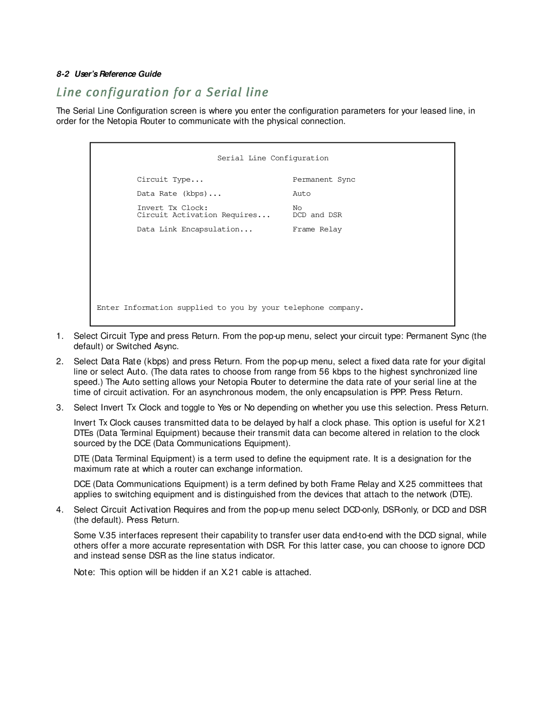
The Serial Line Configuration screen is where you enter the configuration parameters for your leased line, in order for the Netopia Router to communicate with the physical connection.
Serial Line Configuration
Circuit Type... | Permanent Sync |
Data Rate (kbps)... | Auto |
Invert Tx Clock: | No |
Circuit Activation Requires... | DCD and DSR |
Data Link Encapsulation... | Frame Relay |
Enter Information supplied to you by your telephone company.
1.Select Circuit Type and press Return. From the
2.Select Data Rate (kbps) and press Return. From the
3.Select Invert Tx Clock and toggle to Yes or No depending on whether you use this selection. Press Return.
Invert Tx Clock causes transmitted data to be delayed by half a clock phase. This option is useful for X.21 DTEs (Data Terminal Equipment) because their transmit data can become altered in relation to the clock sourced by the DCE (Data Communications Equipment).
DTE (Data Terminal Equipment) is a term used to define the equipment rate. It is a designation for the maximum rate at which a router can exchange information.
DCE (Data Communications Equipment) is a term defined by both Frame Relay and X.25 committees that applies to switching equipment and is distinguished from the devices that attach to the network (DTE).
4.Select Circuit Activation Requires and from the
Some V.35 interfaces represent their capability to transfer user data
Note: This option will be hidden if an X.21 cable is attached.