Making the Physical Connections
Netopia R5000 Series Router status lights
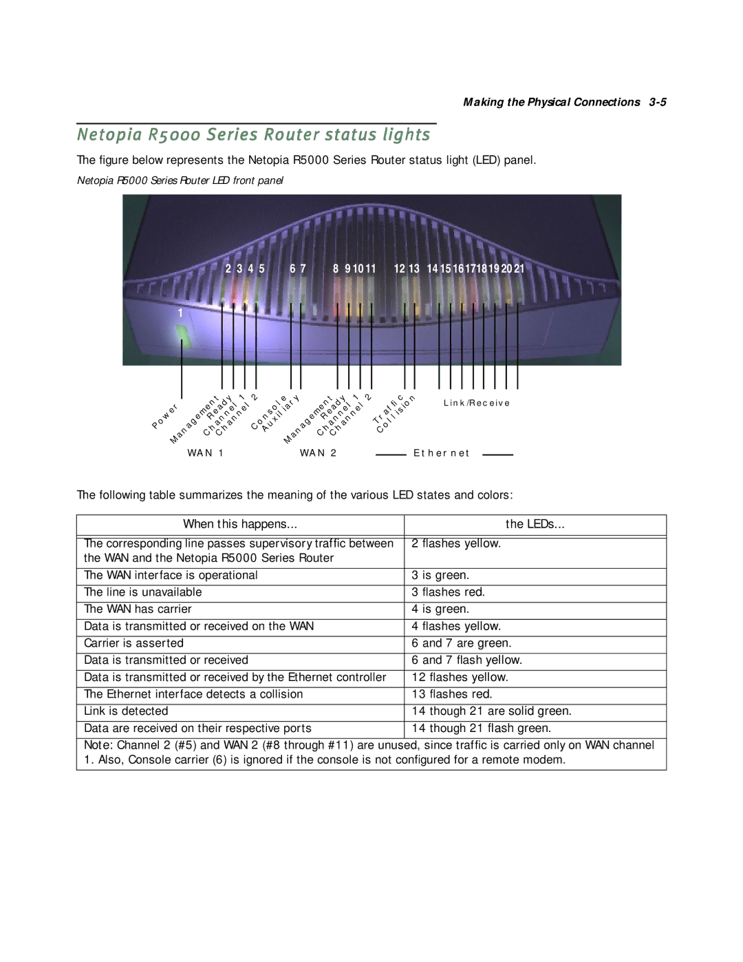
The figure below represents the Netopia R5000 Series Router status light (LED) panel.
Netopia R5000 Series Router LED front panel
2 | 3 4 5 | 6 7 | 8 | 9 10 11 | 12 13 | 14 15 16171819 2021 |
1
|
|
|
|
|
| 1 | 2 |
| ANAGEMENT | 1 | 2 | |||
|
| ANAGEMENT | ONSOLE | |||||||||||
|
|
|
|
|
| |||||||||
| OWER |
|
| EADY |
|
|
|
|
| EADY |
|
| ||
P |
|
|
| HANNELHANNEL C | AUXILIARY |
| HANNELHANNEL |
| ||||||
|
|
| R |
|
|
|
|
| R |
|
|
| ||
| M |
| C |
| C |
|
| M |
| C |
| C |
|
|
|
| WAN 1 |
|
|
| WAN 2 |
|
| ||||||
|
|
|
|
|
|
|
|
| ||||||
| C |
|
T OLLISION | LINK/RECEIVE | |
fi |
| |
RAF |
|
|
C |
|
|
ETHERNET
The following table summarizes the meaning of the various LED states and colors:
When this happens... | the LEDs... |
|
|
|
|
The corresponding line passes supervisory traffic between | 2 flashes yellow. |
the WAN and the Netopia R5000 Series Router |
|
|
|
The WAN interface is operational | 3 is green. |
|
|
The line is unavailable | 3 flashes red. |
|
|
The WAN has carrier | 4 is green. |
|
|
Data is transmitted or received on the WAN | 4 flashes yellow. |
|
|
Carrier is asserted | 6 and 7 are green. |
|
|
Data is transmitted or received | 6 and 7 flash yellow. |
|
|
Data is transmitted or received by the Ethernet controller | 12 flashes yellow. |
|
|
The Ethernet interface detects a collision | 13 flashes red. |
|
|
Link is detected | 14 though 21 are solid green. |
|
|
Data are received on their respective ports | 14 though 21 flash green. |
|
|
Note: Channel 2 (#5) and WAN 2 (#8 through #11) are unused, since traffic is carried only on WAN channel 1. Also, Console carrier (6) is ignored if the console is not configured for a remote modem.