B-4 User’s Reference Guide
Network configuration
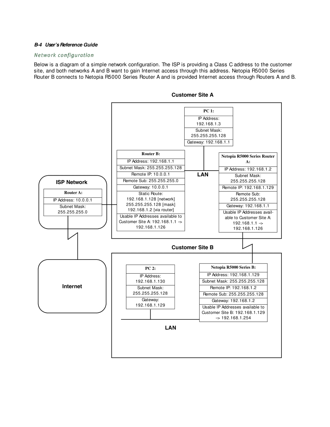
Below is a diagram of a simple network configuration. The ISP is providing a Class C address to the customer site, and both networks A and B want to gain Internet access through this address. Netopia R5000 Series Router B connects to Netopia R5000 Series Router A and is provided Internet access through Routers A and B.
Customer Site A
ISP Network
Router A:
IP Address: 10.0.0.1
Subnet Mask:
255.255.255.0
Router B:
IP Address: 192.168.1.1
Subnet Mask: 255.255.255.128
Remote IP: 10.0.0.1
Remote Sub: 255.255.255.0
Gateway: 10.0.0.1
Static Route:
192.168.1.128 [network] 255.255.255.128 [mask] 192.168.1.2 [via router]
Usable IP Addresses available to Customer Site A: 192.168.1.1
PC 1:
IP Address:
192.168.1.3
Subnet Mask:
255.255.255.128
Gateway: 192.168.1.1
|
|
|
|
|
|
|
| Netopia R5000 Series Router |
|
| A: |
|
|
|
|
| IP Address: 192.168.1.2 |
LAN |
| |
Subnet Mask: | ||
|
| 255.255.255.128 |
|
|
|
|
| Remote IP: 192.168.1.129 |
|
|
|
|
| Remote Sub: |
|
| 255.255.255.128 |
|
|
|
|
| Gateway: 192.168.1.1 |
|
|
|
|
| Usable IP Addresses avail- |
|
| able to Customer Site A: |
|
| 192.168.1.1 |
|
| 192.168.1.126 |
|
|
|
Customer Site B
Internet
PC 2:
IP Address:
192.168.1.130
Subnet Mask:
255.255.255.128
Gateway:
192.168.1.129
LAN
Netopia R5000 Series B:
IP Address: 192.168.1.129
Subnet Mask: 255.255.255.128
Remote IP: 192.168.1.2
Remote Sub: 255.255.255.128
Gateway: 192.168.1.2
Usable IP Addresses available to Customer Site B: 192.168.1.129