Using the BayStack 410-24T 10BASE-T Switch
Verifying the Installation
When power is applied to the switch,
Verifying the Installation Using the LEDs
To verify the installation using the LEDs, check that the switch
Table 2-1. Power-Up Sequence
Stage Description | LED indication |
1Immediately after AC power is applied to the switch, DC power is available to the switch’s internal circuitry.
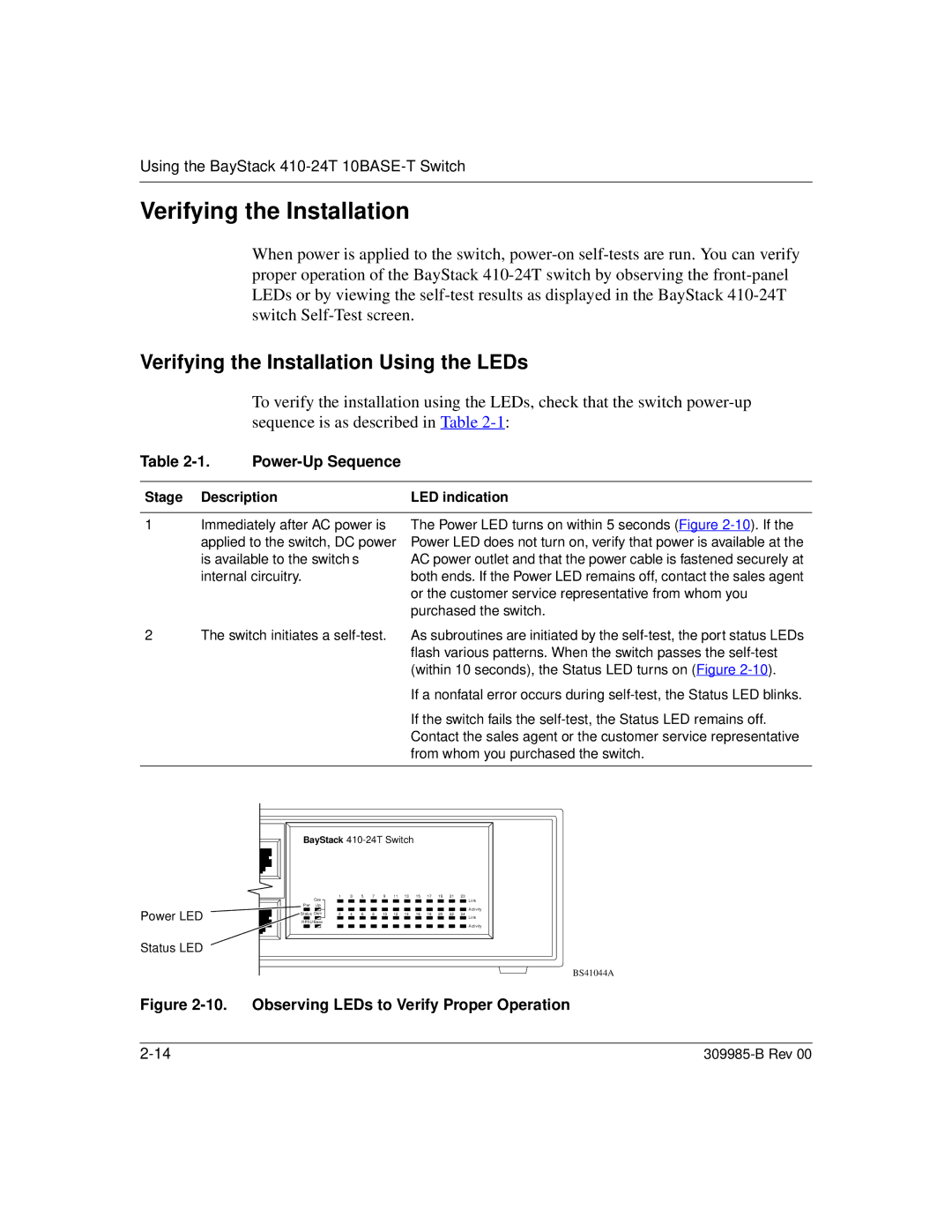
The Power LED turns on within 5 seconds (Figure
2 The switch initiates a
If a nonfatal error occurs during
If the switch fails the
Power LED
Status LED
BayStack
|
| Cas | 1 |
| 3 |
| 5 |
| 7 |
| 9 |
| 11 | 13 |
| 15 |
| 17 |
| 19 |
| 21 |
| 23 |
| |
|
|
|
|
|
|
|
|
|
|
|
|
|
|
|
|
|
|
|
|
|
|
|
|
| Link | |
Pwr Up |
|
|
|
|
|
|
|
|
|
|
|
|
|
|
|
|
|
|
|
|
|
|
| Activity | ||
|
|
|
|
|
|
|
|
|
|
|
|
|
|
|
|
|
|
|
|
|
|
|
|
|
|
|
Status Dwn | 2 |
| 4 |
| 6 |
| 8 |
| 10 |
| 12 | 14 |
| 16 |
| 18 |
| 20 |
| 22 |
| 24 | Link | |||
|
|
|
|
|
|
|
|
|
|
|
|
|
|
|
|
|
|
|
|
|
|
|
|
|
| |
RPSU Base
Activity
BS41044A
