Introduction to the BayStack 410-24T Switch
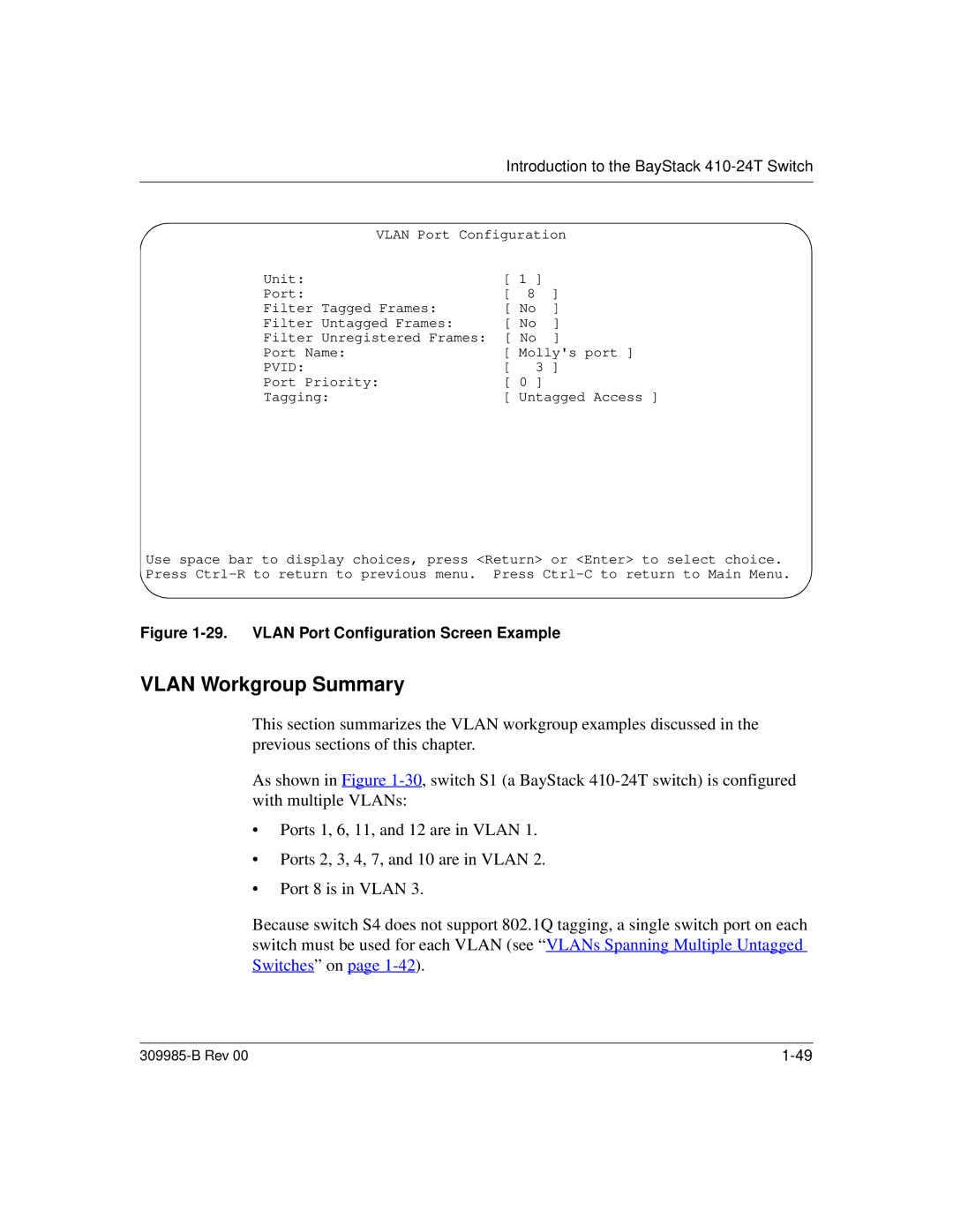
VLAN Port Configuration
Unit: | [ 1 | ] |
|
Port: | [ 8 | ] | |
Filter Tagged Frames: | [ No | ] | |
Filter Untagged Frames: | [ No | ] | |
Filter Unregistered Frames: | [ No | ] | |
Port Name: | [ Molly's port ] | ||
PVID: | [ | 3 ] | |
Port Priority: | [ 0 | ] |
|
Tagging: | [ Untagged Access ] | ||
Use space bar to display choices, press <Return> or <Enter> to select choice. Press
Figure 1-29. VLAN Port Configuration Screen Example
VLAN Workgroup Summary
This section summarizes the VLAN workgroup examples discussed in the previous sections of this chapter.
As shown in Figure
•Ports 1, 6, 11, and 12 are in VLAN 1.
•Ports 2, 3, 4, 7, and 10 are in VLAN 2.
•Port 8 is in VLAN 3.
Because switch S4 does not support 802.1Q tagging, a single switch port on each switch must be used for each VLAN (see “VLANs Spanning Multiple Untagged Switches” on page
|
