Using the BayStack
Cascade A Out Connector
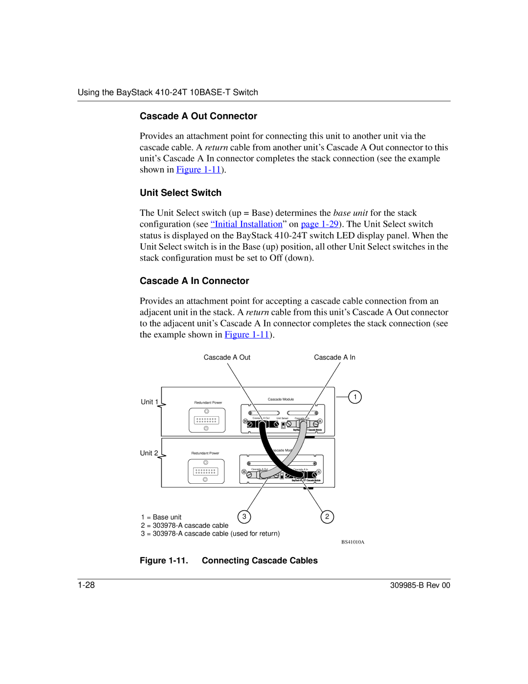
Provides an attachment point for connecting this unit to another unit via the cascade cable. A return cable from another unit’s Cascade A Out connector to this unit’s Cascade A In connector completes the stack connection (see the example shown in Figure
Unit Select Switch
The Unit Select switch (up = Base) determines the base unit for the stack configuration (see “Initial Installation” on page
Cascade A In Connector
Provides an attachment point for accepting a cascade cable connection from an adjacent unit in the stack. A return cable from this unit’s Cascade A Out connector to the adjacent unit’s Cascade A In connector completes the stack connection (see the example shown in Figure
Cascade A Out | Cascade A In |
Unit 1
Cascade Module | 1 |
Redundant Power
| Cascade A Out | Unit Select | Cascade A In |
| ||||
|
|
|
|
|
|
|
|
|
|
|
|
|
|
|
|
|
|
|
|
|
|
|
|
|
|
|
Unit 2
Cascade Module
Redundant Power
| Cascade A Out | Unit Select | Cascade A In | |||||||
|
|
|
|
|
|
|
|
|
|
|
|
|
|
|
|
|
|
|
|
|
|
1 | = Base unit | 3 | 2 |
2 | = |
|
|
3 | = |
| |
BS41010A