Using the BayStack
In Figure
|
|
| PVID = 2 |
| |||
|
|
|
| ||||
Tagged packet |
| ||||||
4 | |||||||
|
|
|
|
|
| ||
CRC | Data | Tag | SA | DA |
| Port | |
|
| ||||||
|
|
|
|
|
|
| |
|
|
|
|
| |||
| Before |
| |||||
|
| ||||||
Port 1 |
| Port 2 |
| Port 3 |
| 802.1Q Switch | |||
|
|
|
|
|
Port 6 |
| Port 7 |
| Port 8 |
 Port 5
Tagged member of VLAN 2
Untagged member of VLAN 2
BS41018A
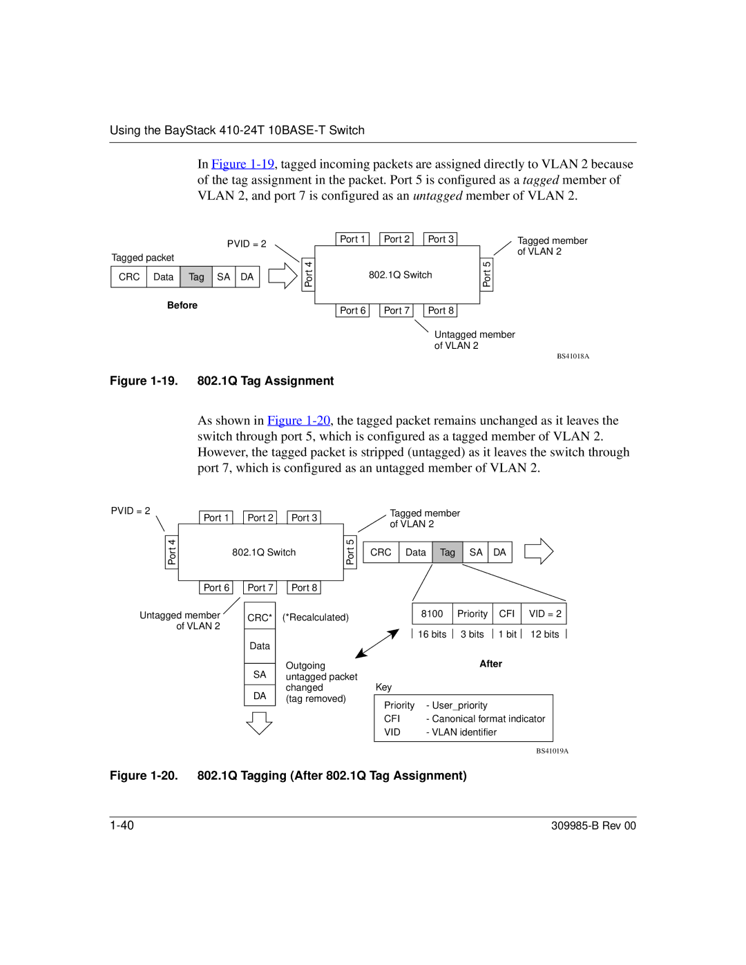
Figure 1-19. 802.1Q Tag Assignment
As shown in Figure
PVID = 2
Port 4![]()
Port 1 |
| Port 2 |
| Port 3 |
| 802.1Q Switch | |||
|
|
|
|
|
Port 6 |
| Port 7 |
| Port 8 |
![]() Port 5
Port 5
Tagged member of VLAN 2
CRC Data Tag SA DA
Untagged member | CRC* | (*Recalculated) |
of VLAN 2 |
|
|
Data |
| |
|
| |
| SA | Outgoing |
| untagged packet | |
|
| changed |
| DA | |
| (tag removed) |
|
| 8100 |
| Priority |
|
| CFI |
| VID = 2 |
| ||
|
|
|
|
|
|
|
|
|
|
|
| |
|
| 16 bits |
| 3 bits |
|
| 1 bit |
| 12 bits |
|
| |
|
|
|
|
|
| |||||||
|
|
|
| After |
|
|
|
|
| |||
Key |
|
|
|
|
|
|
|
|
|
|
| |
Priority | - User_priority |
|
|
|
|
|
| |||||
|
|
|
|
|
| |||||||
CFI | - Canonical format indicator |
|
|
| ||||||||
VID | - VLAN identifier |
|
|
|
|
|
| |||||
|
|
|
|
|
|
|
|
|
|
|
|
|
BS41019A