Nortel Networks 24T manual MultiLink Trunks, Switch-to-Switch Trunk Configuration Example

Models: 24T

1 310
Download 310 pages 27.19 Kb
Page 89
Image 89

Introduction to the BayStack 410-24T Switch

MultiLink Trunks

A MultiLink Trunk (MLT)1 allows you to group up to four switch ports together to form a link to another switch or server, thus increasing aggregate throughput of the interconnection between the devices (up to 800 Mb/s in full-duplex mode with optional 100BASE-T/F MDAs installed). You can configure up to six MultiLink Trunks. The MLT members can reside on a single unit or on multiple units within the same stack configuration as a distributed trunk. MLT software detects misconfigured (or broken) trunk links and redirects traffic on the misconfigured or broken trunk link to other trunk members within that MLT.

You can use the MultiLink Trunk Configuration screen to create switch-to-switch and switch-to-server MLT links (see Figure 1-38 and Figure 1-39).

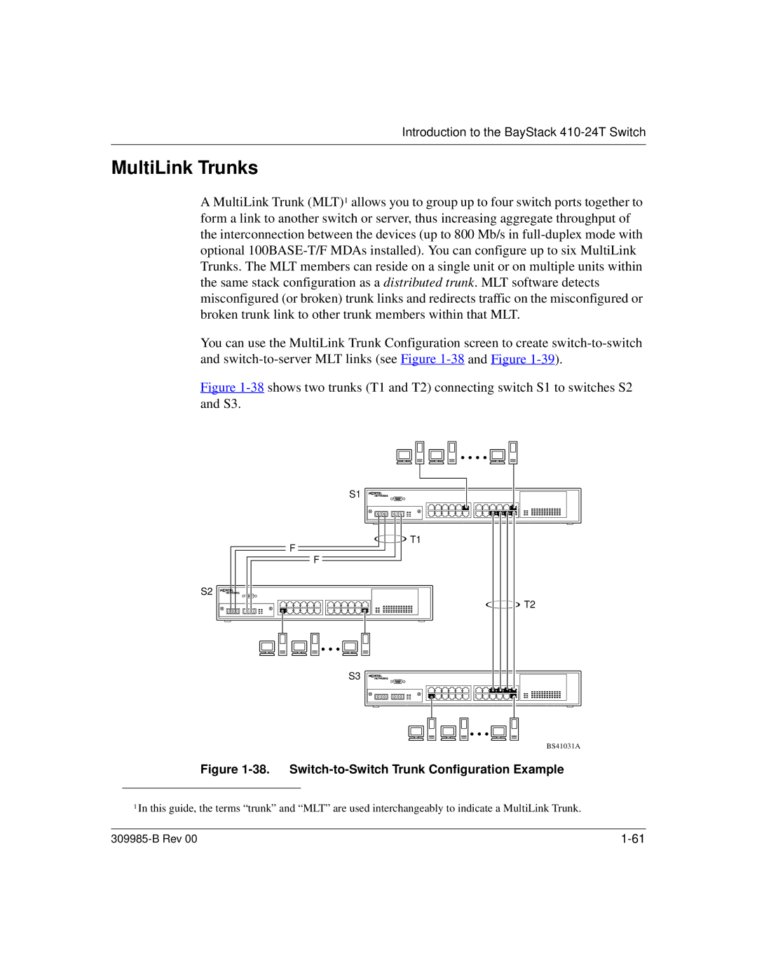
Figure 1-38 shows two trunks (T1 and T2) connecting switch S1 to switches S2 and S3.

S1

T1

F

F

S2

T2

S3

BS41031A

Figure 1-38. Switch-to-Switch Trunk Configuration Example

1In this guide, the terms “trunk” and “MLT” are used interchangeably to indicate a MultiLink Trunk.

309985-B Rev 00

1-61

Page 89
Image 89
Nortel Networks 24T manual MultiLink Trunks, Switch-to-Switch Trunk Configuration Example