Introduction to the BayStack 410-24T Switch
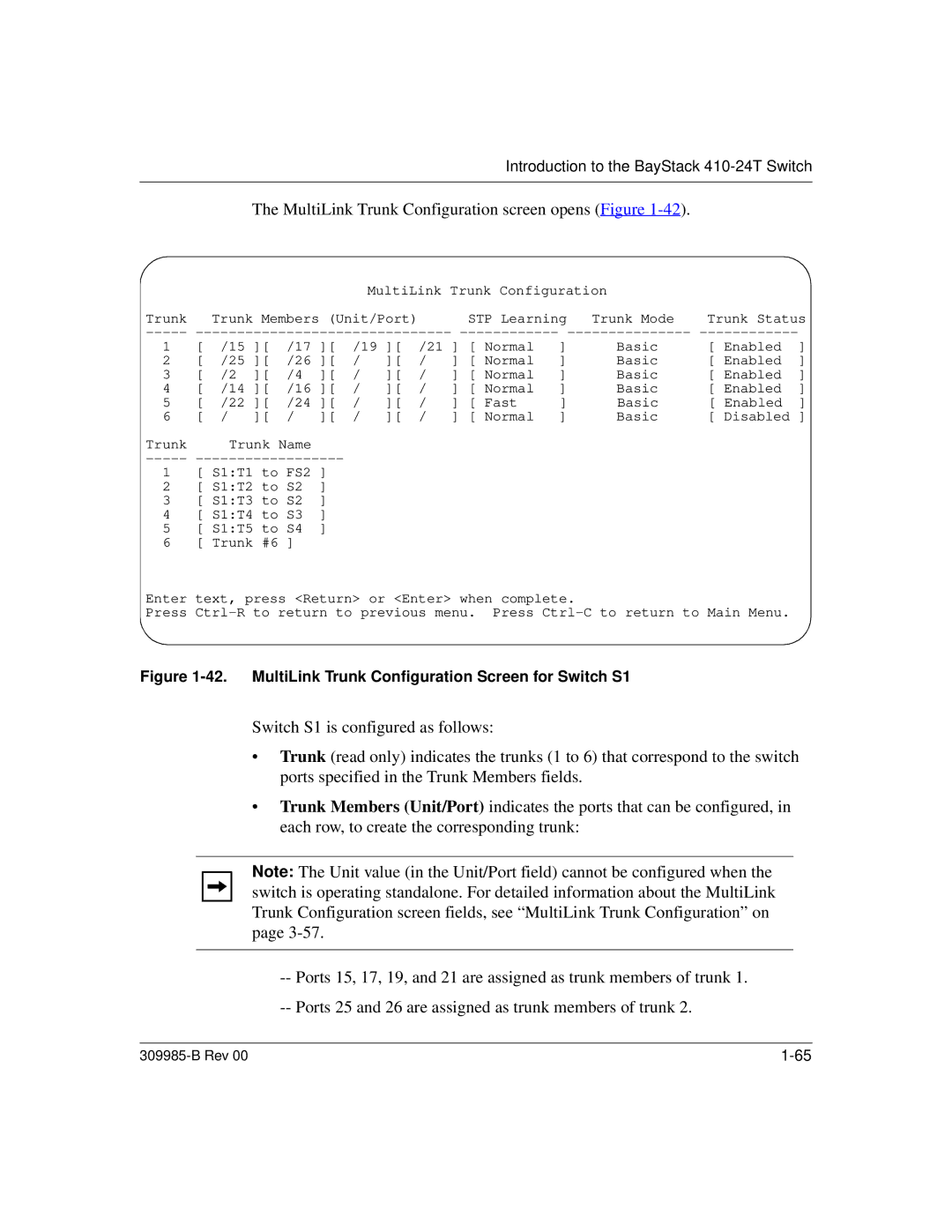
The MultiLink Trunk Configuration screen opens (Figure 1-42).
MultiLink Trunk Configuration |
| |
Trunk Trunk Members (Unit/Port) | STP Learning Trunk Mode | Trunk Status |
1 | [ | /15 ][ | /17 ][ | /19 ][ | /21 | ] [ Normal | ] | Basic | [ Enabled | ] | |||
2 | [ | /25 ][ | /26 ][ | / | ][ | / | ] [ Normal | ] | Basic | [ Enabled | ] | ||
3 | [ | /2 | ][ | /4 | ][ | / | ][ | / | ] [ Normal | ] | Basic | [ Enabled | ] |
4 | [ | /14 ][ | /16 ][ | / | ][ | / | ] [ Normal | ] | Basic | [ Enabled | ] | ||
5 | [ | /22 ][ | /24 ][ | / | ][ | / | ] [ Fast | ] | Basic | [ Enabled | ] | ||
6 | [ | / | ][ | / | ][ | / | ][ | / | ] [ Normal | ] | Basic | [ Disabled ] | |
Trunk |
| Trunk Name |
|
|
|
|
|
|
|
|
| ||
-----
1 [ S1:T1 to FS2 ]
2 [ S1:T2 to S2 ]
3 [ S1:T3 to S2 ]
4 [ S1:T4 to S3 ]
5 [ S1:T5 to S4 ]
6 [ Trunk #6 ]
Enter text, press <Return> or <Enter> when complete.
Press
Figure 1-42. MultiLink Trunk Configuration Screen for Switch S1
Switch S1 is configured as follows:
•Trunk (read only) indicates the trunks (1 to 6) that correspond to the switch ports specified in the Trunk Members fields.
•Trunk Members (Unit/Port) indicates the ports that can be configured, in each row, to create the corresponding trunk:
Note: The Unit value (in the Unit/Port field) cannot be configured when the switch is operating standalone. For detailed information about the MultiLink Trunk Configuration screen fields, see “MultiLink Trunk Configuration” on page
| |
| |
|
|
|