Controls and Connectors
2.3 Controls and Connectors
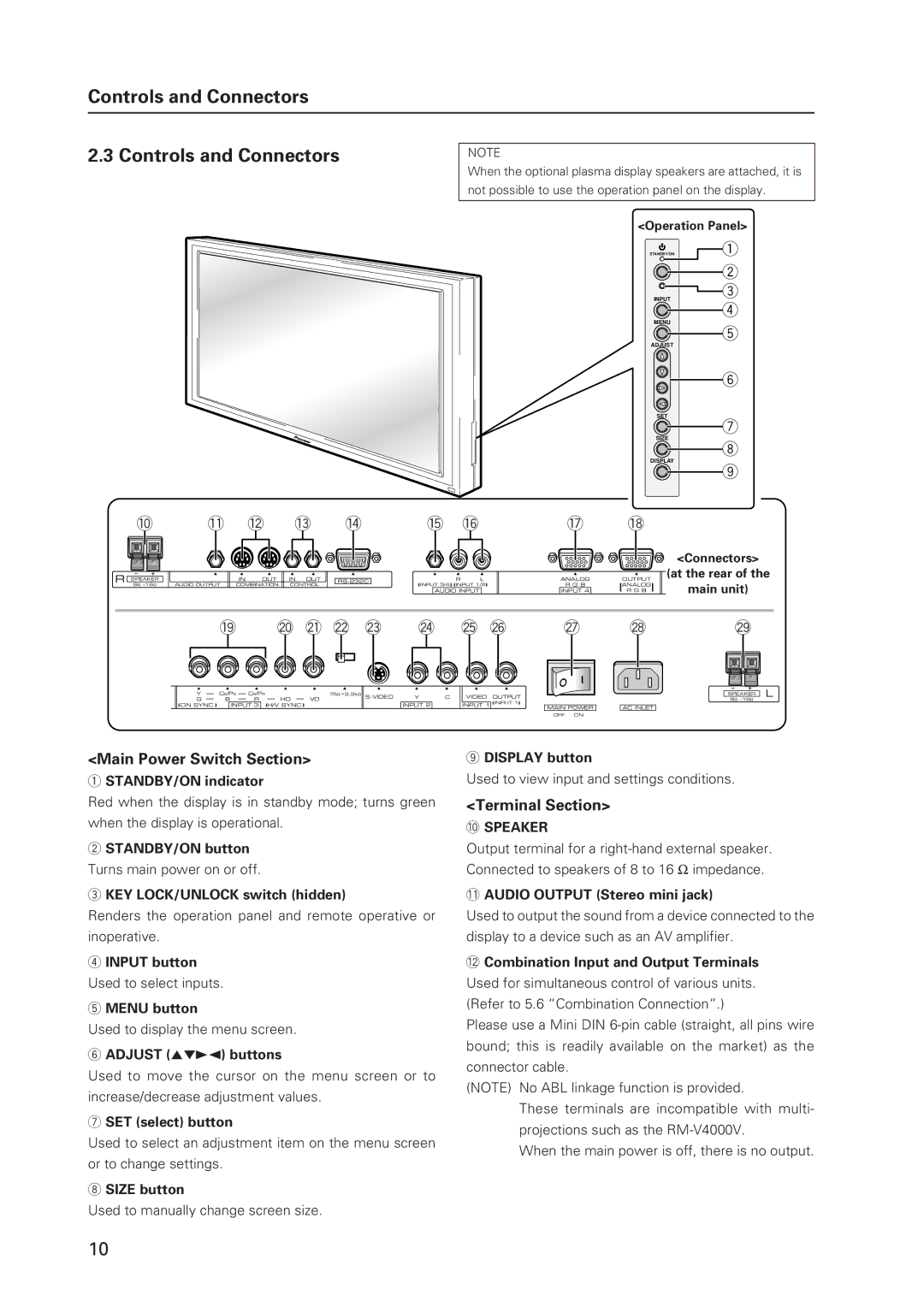
NOTE
When the optional plasma display speakers are attached, it is
not possible to use the operation panel on the display.
<Operation Panel>
STANDBY/ON | 1 |
2
![]() 3
3
INPUT
4
MENU
5
ADJUST
6
SET
7
SIZE
8
DISPLAY
9
0 | - = ~ ! | @ # | $ % |
<Connectors> |
R SPEAKER 8Ω ~16Ω
| IN | OUT | IN OUT |
AUDIO OUTPUT | COMBINATION | CONTROL | |
R L
![]() INPUT 3/4
INPUT 3/4![]()
![]() INPUT 1/2
INPUT 1/2![]()
AUDIO INPUT
ANALOG | OUTPUT |
R G B | ANALOG |
INPUT 4 | R G B |
(at the rear of the
main unit)
^ & * ( ) _ + ¡ |
| ™ | £ | ¢ |
| |||||||||||||||||||||||||||||
|
|
|
|
|
|
|
|
|
|
|
|
|
|
|
|
|
|
|
|
|
|
|
|
|
|
|
|
|
|
|
|
|
|
|
|
|
|
|
|
|
|
|
|
|
|
|
|
|
|
|
|
|
|
|
|
|
|
|
|
|
|
|
|
|
|
|
|
|
|
|
|
|
|
|
|
|
|
|
|
|
|
|
|
|
|
|
|
|
|
|
|
|
|
|
|
|
|
|
|
|
|
|
|
|
|
|
|
|
|
|
|
|
|
|
|
|
|
|
|
|
|
|
|
|
|
|
|
|
|
|
|
|
|
|
|
|
|
|
|
|
|
|
|
|
|
|
|
|
|
|
|
|
|
|
|
|
|
|
|
|
|
|
|
|
|
|
|
|
|
|
|
|
|
|
Y |
| CB/PB |
| CR/PR |
|
|
| 75Ω 2.2kΩ | |||
|
|
|
|
| |||||||
G |
| B |
| R |
| HD |
| VD |
| ||
ON SYNC |
| INPUT 3 |
| H/V SYNC |
|
| |||||
Y
INPUT 2
C
VIDEO OUTPUT INPUT 1![]()
![]() INPUT 1
INPUT 1![]()
MAIN POWER |
| AC INLET |
OFF ON |
|
|
SPEAKER L 8Ω ~16Ω
<Main Power Switch Section>
1STANDBY/ON indicator
Red when the display is in standby mode; turns green when the display is operational.
2STANDBY/ON button
Turns main power on or off.
3KEY LOCK/UNLOCK switch (hidden)
Renders the operation panel and remote operative or inoperative.
4INPUT button
Used to select inputs.
5MENU button
Used to display the menu screen.
6ADJUST (5∞32) buttons
Used to move the cursor on the menu screen or to increase/decrease adjustment values.
7SET (select) button
Used to select an adjustment item on the menu screen or to change settings.
8SIZE button
Used to manually change screen size.
9DISPLAY button
Used to view input and settings conditions.
<Terminal Section>
0SPEAKER
Output terminal for a
-AUDIO OUTPUT (Stereo mini jack)
Used to output the sound from a device connected to the display to a device such as an AV amplifier.
=Combination Input and Output Terminals
Used for simultaneous control of various units. (Refer to 5.6 “Combination Connection”.)
Please use a Mini DIN
(NOTE) No ABL linkage function is provided.
These terminals are incompatible with multi- projections such as the
When the main power is off, there is no output.
10