RS-232C Adjustment Mode
5.5.3 ID assignment
When a connection is made, this feature assigns an ID. ID assignment is performed in the PC.
Commands: <IDC> (ID CLEAR) | Clears assigned IDs. |
<IDS> (ID SET) | Assigns IDs |
IDS is only effective when an ID has not been assigned.
It is assigned from a unit close to the PC.
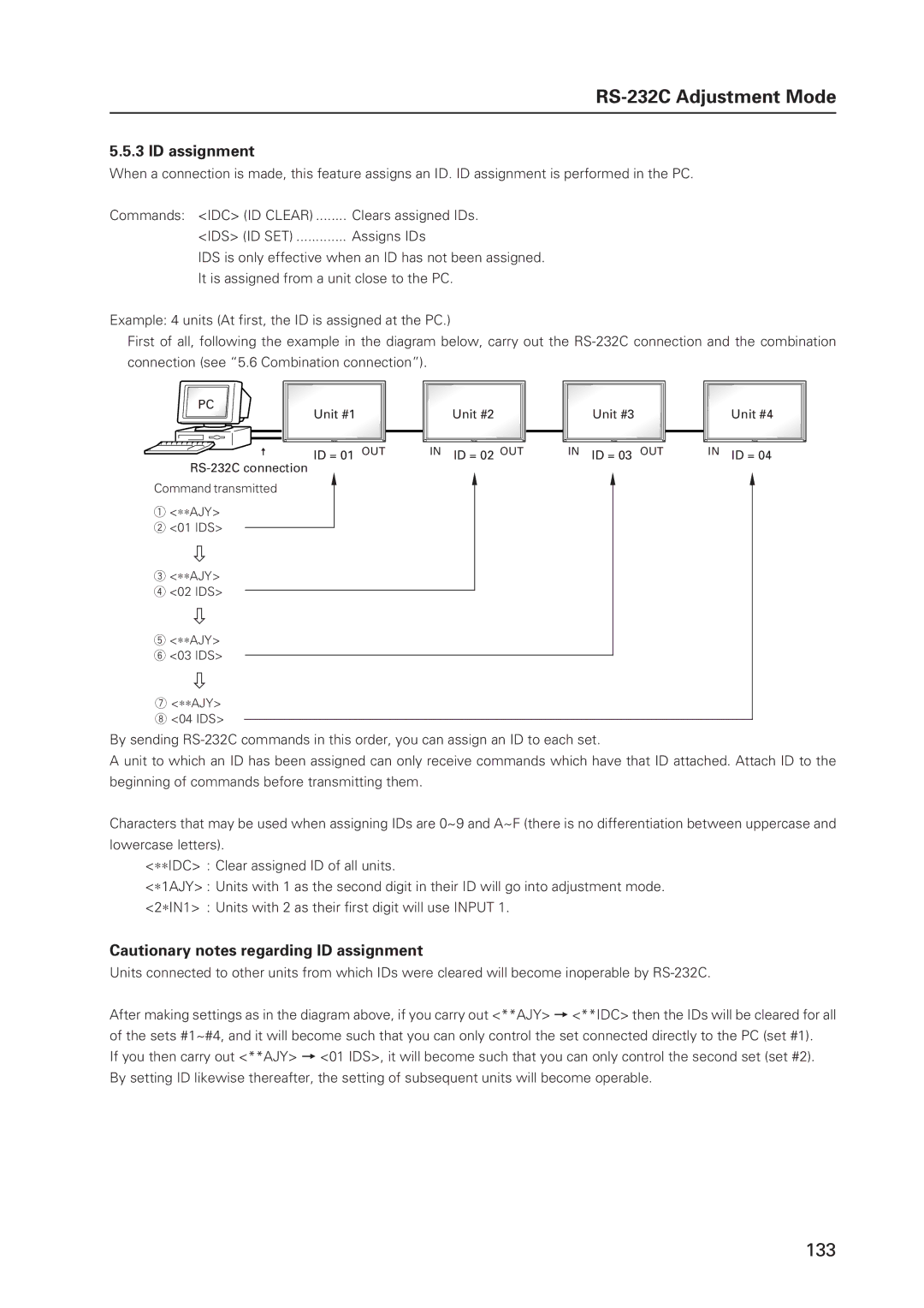
Example: 4 units (At first, the ID is assigned at the PC.)
First of all, following the example in the diagram below, carry out the
PC
| Unit #1 |
± | ID = 01 OUT |
Command transmitted
1<∗∗AJY>
2 <01 IDS>
‘
3<∗∗AJY>
4 <02 IDS>
‘
5<∗∗AJY>
6 <03 IDS>
‘
7<∗∗AJY>
8 <04 IDS>
Unit #2
IN ID = 02 OUT
Unit #3 |
|
|
| Unit #4 |
|
|
|
|
|
|
|
|
|
|
IN ID = 03 OUT |
| IN ID = 04 | ||
By sending
A unit to which an ID has been assigned can only receive commands which have that ID attached. Attach ID to the beginning of commands before transmitting them.
Characters that may be used when assigning IDs are 0~9 and A~F (there is no differentiation between uppercase and lowercase letters).
<∗∗IDC> : Clear assigned ID of all units.
<∗1AJY> : Units with 1 as the second digit in their ID will go into adjustment mode.
<2∗IN1> : Units with 2 as their first digit will use INPUT 1.
Cautionary notes regarding ID assignment
Units connected to other units from which IDs were cleared will become inoperable by
After making settings as in the diagram above, if you carry out <**AJY> = <**IDC> then the IDs will be cleared for all of the sets #1~#4, and it will become such that you can only control the set connected directly to the PC (set #1).
If you then carry out <**AJY> = <01 IDS>, it will become such that you can only control the second set (set #2). By setting ID likewise thereafter, the setting of subsequent units will become operable.
133
