RS-232C Adjustment Mode
5.5.2Interface
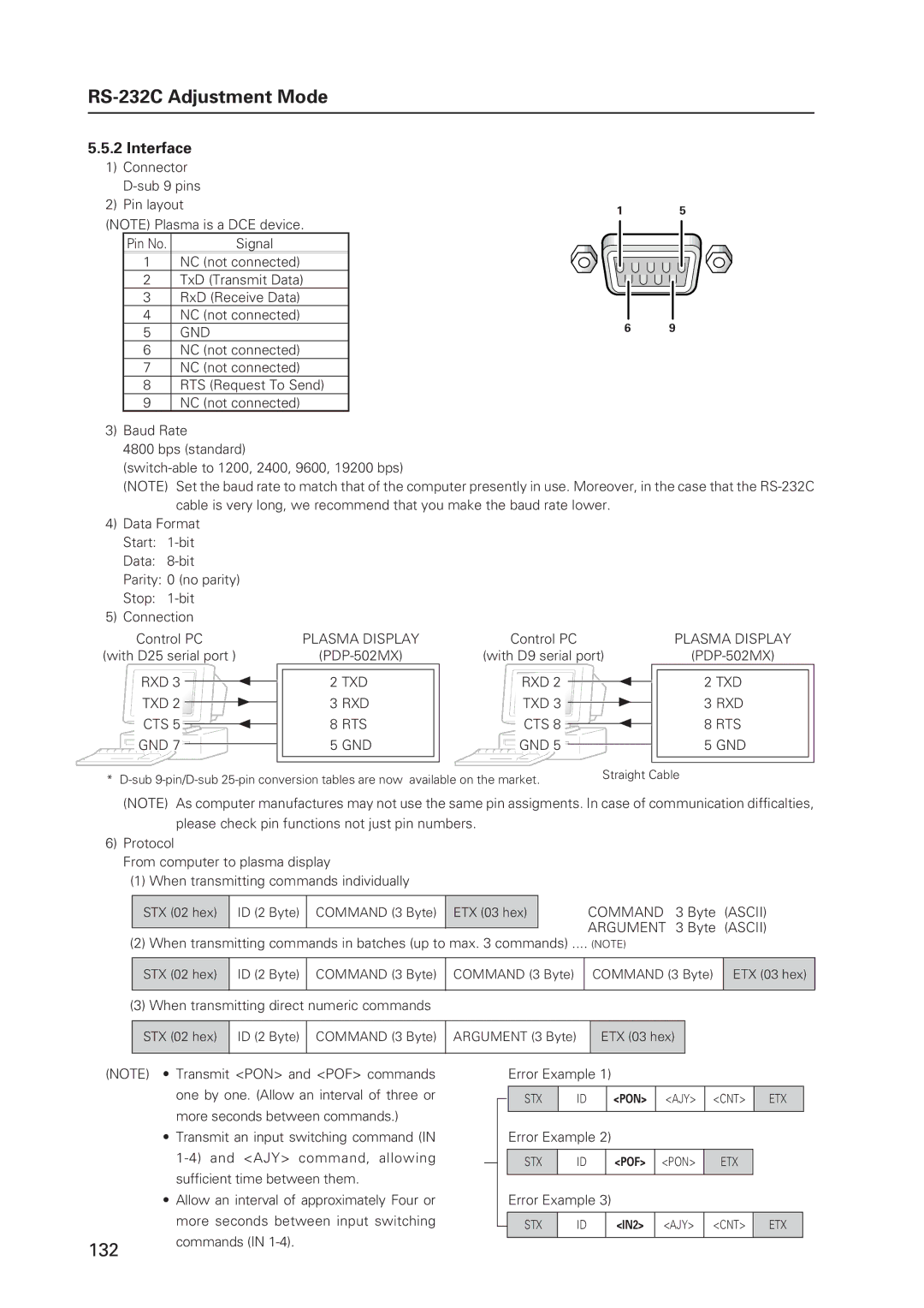
1) Connector
2) Pin layout
(NOTE) Plasma is a DCE device.
Pin No. | Signal |
|
|
1 | NC (not connected) |
2 | TxD (Transmit Data) |
3 | RxD (Receive Data) |
4 | NC (not connected) |
5 | GND |
6 | NC (not connected) |
7 | NC (not connected) |
8 | RTS (Request To Send) |
9 | NC (not connected) |
1 5
6 9
3)Baud Rate
4800 bps (standard)
(NOTE) Set the baud rate to match that of the computer presently in use. Moreover, in the case that the
4)Data Format Start:
5)Connection
Control PC | PLASMA DISPLAY | Control PC | PLASMA DISPLAY |
(with D25 serial port ) | (with D9 serial port) |
RXD 3 | 2 | 2 TXD | RXD 2 | 2 | 2 TXD |
TXD 2 | 3 | 3 RXD | TXD 3 | 3 | 3 RXD |
CTS 5 | 2 | 8 RTS | CTS 8 | 2 | 8 RTS |
GND 7 |
| 5 GND | GND 5 |
| 5 GND |
* | Straight Cable |
|
(NOTE) As computer manufactures may not use the same pin assigments. In case of communication difficalties, please check pin functions not just pin numbers.
6)Protocol
From computer to plasma display
(1)When transmitting commands individually
STX (02 hex)
ID (2 Byte) COMMAND (3 Byte) ETX (03 hex)
COMMAND 3 Byte (ASCII) ARGUMENT 3 Byte (ASCII)
(2) When transmitting commands in batches (up to max. 3 commands) .... (NOTE)
STX (02 hex) ID (2 Byte) COMMAND (3 Byte) COMMAND (3 Byte)
COMMAND (3 Byte) ETX (03 hex)
(3) When transmitting direct numeric commands
STX (02 hex) ID (2 Byte) COMMAND (3 Byte) ARGUMENT (3 Byte)
ETX (03 hex)
(NOTE)
132
•Transmit <PON> and <POF> commands one by one. (Allow an interval of three or more seconds between commands.)
•Transmit an input switching command (IN
•Allow an interval of approximately Four or more seconds between input switching commands (IN
Error Example 1)
STX | ID | <PON> | <AJY> | <CNT> | ETX |
|
|
|
|
|
|
Error Example 2)
STX | ID | <POF> | <PON> | ETX |
|
|
|
|
|
Error Example 3)
| STX | ID | <IN2> | <AJY> | <CNT> | ETX |
| ||||||
|
|
|
|
|
|
|