Integrator Mode
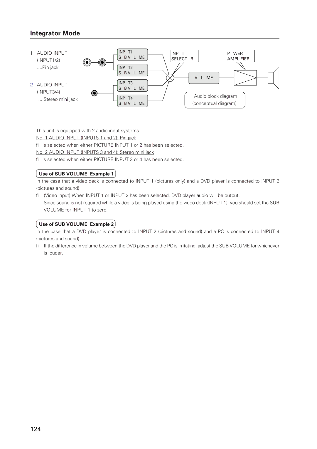
1 AUDIO INPUT | INPUT1 | INPUT | POWER | |
(INPUT1/2) | SUB VOLUME | SELECTOR | AMPLIFIER | |
| ||||
....Pin jack | INPUT2 |
|
| |
| SUB VOLUME |
| VOLUME | |
|
|
| ||
2 AUDIO INPUT | INPUT3 |
|
| |
SUB VOLUME |
|
| ||
(INPUT3/4) |
|
| ||
|
| Audio block diagram | ||
....Stereo mini jack | INPUT4 |
| ||
(conceptual diagram) | ||||
| SUB VOLUME | |||
This unit is equipped with 2 audio input systems
No. 1 AUDIO INPUT (INPUTS 1 and 2): Pin jack
→Is selected when either PICTURE INPUT 1 or 2 has been selected. No. 2 AUDIO INPUT (INPUTS 3 and 4): Stereo mini jack
→Is selected when either PICTURE INPUT 3 or 4 has been selected.
Use of SUB VOLUME: Example 1
In the case that a video deck is connected to INPUT 1 (pictures only) and a DVD player is connected to INPUT 2 (pictures and sound)
→(Video input) When INPUT 1 or INPUT 2 has been selected, DVD player audio will be output.
Since sound is not required while a video is being played using the video deck (INPUT 1), you should set the SUB VOLUME for INPUT 1 to zero.
Use of SUB VOLUME: Example 2
In the case that a DVD player is connected to INPUT 2 (pictures and sound) and a PC is connected to INPUT 4 (pictures and sound)
→If the difference in volume between the DVD player and the PC is irritating, adjust the SUB VOLUME for whichever is louder.
124