Menu Mode
7)Setting the clamp position
Plugging in RGB (G ON SYNC) signals and a sync signal simultaneously may produce inappropriate intensity reproduction, with an
Clamp pulse (a timing pulse necessary for intensity reproduction), is generated in two ways, “a” and “b”, as shown in Figure 1.
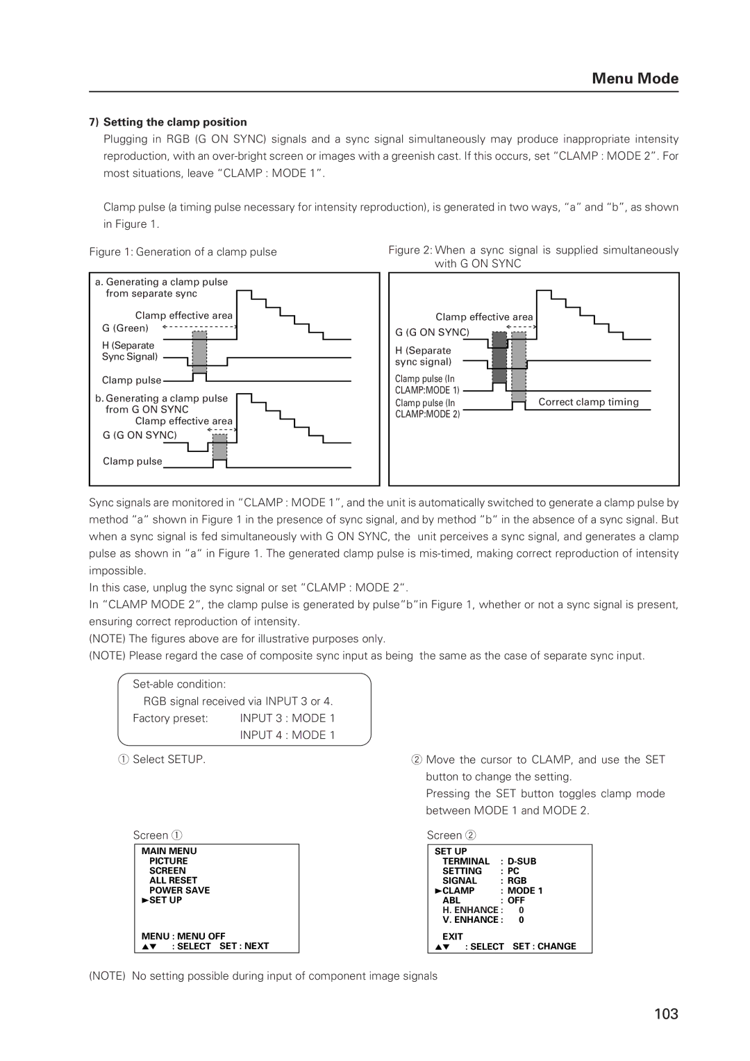
Figure 1: Generation of a clamp pulse
a. Generating a clamp pulse from separate sync
Clamp effective area
G (Green)
H(Separate Sync Signal)
Clamp pulse ![]()
b. Generating a clamp pulse from G ON SYNC
Clamp effective area
G (G ON SYNC)
Figure 2: When a sync signal is supplied simultaneously with G ON SYNC
Clamp effective area |
G (G ON SYNC) |
H (Separate sync signal)
Clamp pulse (In
CLAMP:MODE 1) ![]()
Clamp pulse (In |
|
| Correct clamp timing |
|
| ||
CLAMP:MODE 2) |
|
|
|
Clamp pulse
Sync signals are monitored in “CLAMP : MODE 1”, and the unit is automatically switched to generate a clamp pulse by method “a“ shown in Figure 1 in the presence of sync signal, and by method “b“ in the absence of a sync signal. But when a sync signal is fed simultaneously with G ON SYNC, the unit perceives a sync signal, and generates a clamp pulse as shown in “a“ in Figure 1. The generated clamp pulse is
In this case, unplug the sync signal or set “CLAMP : MODE 2“.
In “CLAMP MODE 2“, the clamp pulse is generated by pulse“b“in Figure 1, whether or not a sync signal is present, ensuring correct reproduction of intensity.
(NOTE) The figures above are for illustrative purposes only.
(NOTE) Please regard the case of composite sync input as being the same as the case of separate sync input.
RGB signal received via INPUT 3 or 4.
Factory preset: INPUT 3 : MODE 1
INPUT 4 : MODE 1
1Select SETUP.
Screen 1
MAIN MENU | CONTRAST : 0 | |
PICTURE | ||
SCREEN | BRIGHT | : 0 |
ALL RESET | COLOR | : 0 |
POWER SAVE | TINT | : 0 |
3SET UP | SHARP | : 0 |
| RESET |
|
MENU : MENU OFF
5∞ 3 : SELECT SET : NEXT
2Move the cursor to CLAMP, and use the SET button to change the setting.
Pressing the SET button toggles clamp mode between MODE 1 and MODE 2.
Screen 2
SET UP |
|
|
TERMINAL | : | |
SETTING | : PC | |
SIGNAL | : RGB | |
3CLAMP | : MODE 1 | |
ABL | : OFF | |
H. ENHANCE : | 0 | |
V. ENHANCE : | 0 | |
EXIT
5∞ 3 : SELECT SET : CHANGE
(NOTE) No setting possible during input of component image signals
103