StorageTek SL500
Page
StorageTekTM SL500 Modular Library System
Sun Microsystems, Inc
USA
Vi SL500 User’s Guide July Revision KA
Summary of Changes
Date Revision Description
Previous Organization
New Organization
Troubleshooting-Information included in previous Chapter
SL500 User’s Guide July Revision KA
Contents
StorageTek Library Console
Revision KA Contents
SL500 Automated Library Operations
Licensing
Capacity on Demand
Library Partitioning
Revision KA Contents
SL Console Diagnostics and Utilities 249
Revision KA Contents
Manual Operations
SL500 Wall Diagrams and Specifications
Web-launched SL Console Server
Glossary 391 Index
Figures
Page
Tables
Xxvi SL500 User’s Guide July Revision KA
Preface
Organization
Alert Messages
Conventions
Example Description of Convention
Related Documentation
Publications Link
SunSolve and Helpful Links
Additional Information
Sun’s external Web Site
Partners Site
Xxxii SL500 User’s Guide July Revision KA
SL500 Introduction
Views and Locations
Revision KA SL500 Introduction
LTO Library Configurations
Library with LTO Storage Cells
LTO Library Internal Addressing
Modules Cells
LTO Storage Cell and Drive Capacities
Maximum Number of Tape Drives
Total # Storage Cells
Adding LTO Storage Cell Capacity
Mixed-Media Library Configurations
Library with Mixed-Media Storage Cells
Mixed-Media Library Internal Addressing
Mixed-Media Storage Cell and Drive Capacities
Adding Mixed-Media Storage Cell Capacity
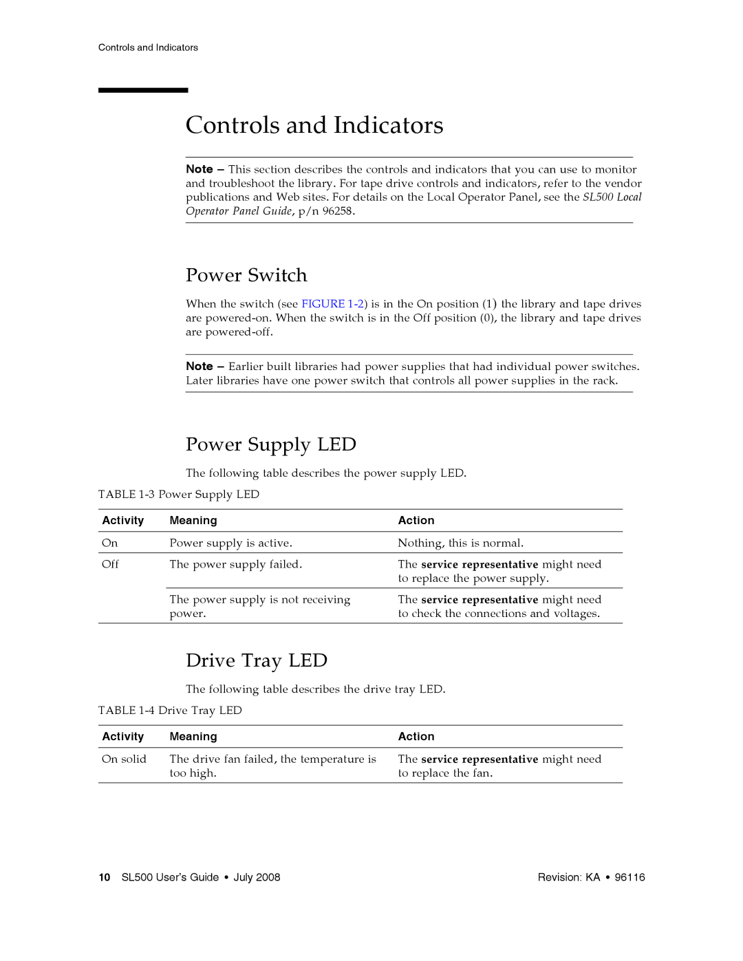
Power Supply LED
Controls and Indicators
Power Switch
Drive Tray LED
Keypad
Buttons/Indicator Description
Indicator
Button
RLC Card Indicators
Indicator Description
Tape Drives and Cartridges
Sdlt 320 Scsi LVD
LTO Tape Drives and Cartridges
Media Label Gen 1 Drive Gen 2 Drive Gen 3 Drive Gen 4* Drive
SDLT/DLT-S4 Tape Drives and Cartridges
Media Sdlt 320 Drive Sdlt 600 Drive DLT-S4* Drive
Cartridge Access Ports
Allow Prevent
Robotics Unit
Robotics Components
Power System
Cooling
Electronics
RLC Card
Interface Cards
Robotics
Safety Features
Cards and Power Supply
Front Door
Interfaces
Library Interfaces Locations
Tape Management Software
26 SL500 User’s Guide July Revision KA
Introduction
SL Console Modes
Activation Password
SL Console Security
User IDs
Log in to the SL Console
Change a User Password
SL Console Usage Tasks
Log Off the SL Console
SL Console Screen Display
Component Name Description
Refresh buttons
Synchronizing the Display With the Controller Database
Modifying the Screen Layout
Display Option Instructions
Enter Data Using the Keypad
Modify Data Using the Keypad
Local Operator Panel
Log in to the Local Operator Panel
Click Log on
Security Considerations
Installation Requirements
Standalone SL Console
User Location Name
Standalone SL Console Installation
Install the Standalone SL Console
License Agreement screen appears
38 SL500 User’s Guide July Revision KA
Revision KA StorageTek Library Console
40 SL500 User’s Guide July Revision KA
Log in to the Standalone SL Console
Standalone SL Console Updates
Enter your login information
Select Start RunSLConsole or Launch RunSLConsole
Web-launched SL Console Updates
Web-launched SL Console
Client Requirements
Choose your login method
Starting the Web-launched SL Console on a Client
SL Console Launch screen appears. Click Launch Now
Opening slc.jnlp popup appears
Specify the action you want to take with the slc.jnlp file
46 SL500 User’s Guide July Revision KA
Revision KA StorageTek Library Console
SL Console Login screen appears
Log in to the Web-launched SL Console Using an Icon
Double-click the slc.jnlp desktop icon on your client
Verify that the Publisher is Sun Microsystems, Inc
Revision KA StorageTek Library Console
52 SL500 User’s Guide July Revision KA
SL Console Reports
Report Types
Generate a Report
Click Update
Report Options Bar
Access the SL Console Help
SL Console Help
Help Navigation
Tips for Using the SL Console Help
Button Action
Automated Mode of Operation
Cartridge Mount and Dismount Activities
Determining When the Library is Not in Automated Mode
Dismount Sequence
Library and Device Status
Communications Failures
Viewing Library Information
CAP Operations
Recovery Moves
Cartridge Management
Ejecting Expired Cleaning Cartridges
Drive Cleaning
Cleaning Cartridges
Automatic Cleaning
Manual Cleaning
Automated Operation Tasks
Library Management Tasks
Task
Display Library Status
Display Library Configuration Information
Set the Library Fibre Channel Port Address
70 SL500 User’s Guide July Revision KA
Display Library Controller Properties
Display Library Physical Configuration
Display Library Statistics
Display a Library Report
Tools Partitions Select Tools Reports
Specified report is displayed
Search a Library Report
Click Search
Revision KA SL500 Automated Library Operations
Save Library Report Data to a File
Click Save
Save popup appears
CAP Management Tasks
Display CAP Summary Information
Display Current CAP Status
Display CAP Properties
Cartridge Management Tasks
Enter Cartridges Through the CAP
Press the CAP Open button on the keypad
Base Module Magazine Comparison
Eject Cartridges Through the CAP
List Library Cartridges
Source Location Mode field, click Volid
Move a Specified Cartridge by Volid
CAP
Click the Start button in the Options Bar
92 SL500 User’s Guide July Revision KA
Source Location Mode field, click Location
Move a Cartridge From a Specified Location
Slot Drive Reserved Slots
Revision KA SL500 Automated Library Operations
96 SL500 User’s Guide July Revision KA
Revision KA SL500 Automated Library Operations
Drive Management Tasks
Display Drive Summary Information
Display Drive Status
Display Drive Properties
Enable or Disable a Drive Port
Display the Media Drive Events Report
Date/Time
Drive Serial Num
Drive Adr
Volid
Drive Type
Drive Cleaning Tasks
Configure Drive Auto Clean
Enter Cleaning or Diagnostic Cartridges
108 SL500 User’s Guide July Revision KA
Eject Cleaning or Diagnostic Cartridges
110 SL500 User’s Guide July Revision KA
Display Cleaning Cartridges
Volid
Display Drive Cleaning Status
Clean a Drive Manually
Confirmation popup appears
Robot Monitoring Tasks
Display Robot Summary Information
Display Robot Status
Display Robot Statistics
Licensing
License Key File
License Installation Process
Licensing Tasks
Licensing Task Summary
Receive a New License Key File
Install a New License on the Target Library
124 SL500 User’s Guide July Revision KA
Display Current Library Licenses
Delete a License Key File
Click the Delete button
Click Yes to begin the deletion
Licensing Screen Reference
Screen
Feature
License Management Current License
Assigned
Sequence Number
Value
Module Number
Nnn Cells Total are Possible Display only
Reboot
Nnn Cells Unlicensed Display only
Delete
License Management Install License
File Name
Serial Number
Install
Product
Sequence #
Browse
License Management Current License
136 SL500 User’s Guide July Revision KA
Capacity on Demand Features Restrictions
Capacity on Demand
Terminology
Planning Library Capacity
Drive Expansion Module DEM
Cartridge Expansion Module CEM after Base Module or DEM
Cartridge Expansion Module CEM after CEM
Cell Assignment Rules
Orphaned Cartridges in Non-Partitioned Libraries
Implementing Changes to Licensed Capacity
Increasing Licensed Capacity
Decreasing Licensed Capacity
Host Notification of Capacity Changes
Partitioning Features and Restrictions
Library Partitioning
Partition Planning
Installing the Partitioning Feature
Partition Configurations
Allocated Storage Capacity
Partition Boundaries
Library Partition Example
Deleting the Partitioning Feature
Resource Group Included Resources
Partitions and Library Resources
Library Resource Addresses
Storage Cells and Drives
Scsi Element Address Examples
Split CAP
Partitions and CAPs
Common CAP
CAP Operations
Orphaned Cartridges in Partitioned Libraries
Partition Configuration Process
Partitioning Process
SL Console Partition Workspace
154 SL500 User’s Guide July Revision KA
Partitioning Task Summary
Partition Configuration Tasks
Review Partitioning Instructions
Select Tools Partitions
Create a Partition
Click OK
Configure a Host-Partition Connection
Click Add Connection
Enter the Initiator Wwpn and LUN Click OK
Design a Partition
Select Tools Partitions Click the Design tab
Revision KA Library Partitioning
Verify Partition Configurations
Options Bar, click Verify
Revision KA Library Partitioning
Resolve Orphaned Cartridges
Commit Partition Configuration Changes
Vary the library offline to Acsls and HSC
Proceed as follows
Revision KA Library Partitioning
Partition Management Tasks
Modify Partition Summary Information
Delete a Partition
Click OK to confirm the deletion
Updates are made as follows
Modify Host-Partition Connection Detail
Revision KA Library Partitioning
Delete a Host-Partition Connection
Click OK to confirm the deletion
Refresh the SL Console Partition Workspace
Reallocate Library Resources
Make a Hardware Change to a Partitioned Library
Partition Report Tasks
Display a Partition Report
Pull-down menu, select the report you want to display
Print Partition Report Data
Click Print
Save Partition Report Data
Click Save to File
CAP Operation Tasks
Enter Cartridges Into a Partitioned Library
Click the Assign CAP Button tab
Revision KA Library Partitioning
Eject Cartridges From a Partitioned Library
Click the Assign CAP Button tab
192 SL500 User’s Guide July Revision KA
Partition Screen Reference
Partition Summary Screens
Partitions-Instructions Step
196 SL500 User’s Guide July Revision KA
Partitions-Summary Step
Allocated Drive Bays
Partition Number
Allocated Storage Cells
Allocated CAP Cells
Storage Cells in Library
Drive Bays in Library
Total CAP cells
Modify Partition
Add Partition
Delete Partition
Add Connection
Partitions-Summary -Add Connection
Connections n
Cancel
Partitions-Summary -Delete Connection
Partitions-Summary -Modify Connection
Buttons
Partitions-Summary -Add Partition
Select a Partition ID
Barcode Presentation
Partitions-Summary -Delete Partition
Partitions-Summary -Modify Partition
Modify Partition n
210 SL500 User’s Guide July Revision KA
Partition Design and Commit Screens
Partitions-Design Step
Add
Partition
Select by
Remove
Unallocated Storage
Unallocated Drive Bays
Unallocated CAPs
Library Map
Verify Results
216 SL500 User’s Guide July Revision KA
Partitions-Design -Verify Results
Following hosts will need re-audited
Following hosts do not have Lun 0 set
Following orphaned cartridges were found
Save
Details
Partitions-Commit Step
Apply
222 SL500 User’s Guide July Revision KA
Partitions-Commit -Confirm Apply
Yes
Partitions-Commit Step Partitions-Design -Verify Results
Partition Report Screens
Partitions-Reports
Please select a report to display
Partitions-Reports-Cartridge Cell and Media Summary
Column
Module
Row
Cell Status
Save to File
Partitions-Reports-Host Connections Summary
CAP Count
Cell Count
Drive Count
Cartridge Count
Display only Partition ID to which the host has a connection
Partitions-Reports-Orphaned Cartridge Report
Explanation
Revision KA Library Partitioning
Partitions-Reports-Partition Details
Available Cells
Bar Code
Assigned Cells
Occupied Cells
Percent Slot Capacity
Partitions-Reports-Partition Summary
242 SL500 User’s Guide July Revision KA
See Also
Partition CAP Operation Screens
Diagnostics CAP-Assign CAP Button
Partitions with common CAP configuration
Partitions with split CAP configuration
See Also
248 SL500 User’s Guide July Revision KA
Library Events
Event Monitors
Library Self-Tests
Library Firmware Upgrades
Firmware Installation Process
Firmware Download Sites
Audits
Physical Audit
Verified Audit
Robot Diagnostic Moves
Target Address Range
Move Access Order
Pool Address Range
Diagnostic Move Control Functions
Select Menu Option
Troubleshooting
Problem What to do
Perform the following procedure
See Remove a Cartridge from a Tape Drive on
Diagnostic and Utility Tasks
Event Monitor Tasks
Display an Event Monitor
Select Tools Monitors Expand the Permanent Monitors folder
SelectTo
Spool Event Monitor Data to a File
To stop spooling, select Monitor Stop Spooling
Following is a sample of the spool file
Display Multiple Monitors
Select
Library Utility Tasks
Perform a Library Self-Test
Reboot the Library
Click OK to continue
Revision KA
Download Code to the Library Controller
Revision KA
Activate Code on the Library Controller
Revision KA
Audit Tasks
Audit the Entire Library
Click the Audit tab
Audit a Range of Cells
278 SL500 User’s Guide July Revision KA
Perform a Verified Audit
Audit Console section displays the progress of the audit
Drive Utility Tasks
Perform a Drive Self-Test
Reboot a Drive
284 SL500 User’s Guide July Revision KA
HandBot Utility Tasks
Define a Diagnostic Move
Click Next
Sequence screen appears
Click Finish to complete the setup
Manage Diagnostic Move Definitions
Select Option
Save a Diagnostic Move to a File
Save popup appears
Start a Diagnostic Move
Revision KA
Monitor and Control Open Diagnostic Moves
Status Indicators Description Valid Values
Select Option
298 SL500 User’s Guide July Revision KA
Snmp Support
Trap Levels
Access Control
Port Control
Trap Level Number Description
Snmp Configuration and Usage Tasks
Add Snmp Users
Delete Snmp Users
Add Trap Recipients
See Trap Levels on page 299 for details
Delete Trap Recipients
Set Up Port Control
Transfer the Library MIB File
Click Transfer
Library Safety
Manual Operations
Manual Operation Tasks
General Library Operation Tasks
Power Off the Library
Power On the Library
Return the Library to Ready Status
Open the Front Door With Power
Open the Front Door Without Power
Revision KA Manual Operations
Secure the Front Door With Power
Secure the Front Door Without Power
Cartridge Handling Tasks
Locate and Remove a Cartridge
Insert Cartridges into Storage Cells
Check the cartridges to make sure they are correctly labeled
Revision KA Manual Operations
Insert a Cartridge into a Tape Drive
Remove a Cartridge from a Tape Drive
Ibmhp
326 SL500 User’s Guide July Revision KA
Remove a Cartridge from the Gripper Assembly
If the hand assembly is facing right
Manual Release Screw Gripper belt and pulleys Release screw
Replace a Cleaning Cartridge
330 SL500 User’s Guide July Revision KA
SL500 Wall Diagrams Specifications
LTO Configurations
Figure A-1 Base Module LTO Cells
Figure A-2 LTO Cell Locations for Firmware Site Mapping
113 125
336 SL500 User’s Guide July Revision KA
Mixed-Media Configurations
Figure A-5 Base Module Mixed-Media Cells
Figure A-6 Mixed-Media Firmware Cell Mapping
Figure A-7 Mixed-Media Scsi Element Numbering Mapping
L204561
Specifications
Figure A-9 Library and Rack Dimensions
Figure A-10 Library and Rack Clearances
Library Environment
Library Component Weights
Component Weight
Measurements Operating Storage Transporting
Two LTO Tape Drives
Power Specifications
Input voltage 100-240 VAC, single phase
Four LTO Tape Drives
Cartridge Information
Handling Cartridges
Inspecting Cartridges
Maintaining Cartridges
Cartridge Requirements
Ordering Cartridges and Labels
LTO Ultrium Cartridges
Valid Labels
Label Type of Cartridge
Figure B-2 LTO Cartridge Labels
Write-protect Switch
Figure B-3 Apply the Utrium Cartridge Label
Figure B-4 Set the LTO Write-Protect Switch Write-protected
SDLT/DLT-S4 Cartridges
Figure B-5 Sdlt Cartridge Components
Figure B-6 Apply the Sdlt Cartridge Label
CLN + S
Figure B-8 Set the Sdlt Write-Protect Switch
Apply a Label to a Cartridge 360
Apply a Label to a Cartridge
Security Considerations
Server Requirements
Server Installation and Management
Download the Java System Web Server
Revision KA Appendix C Web-launched SL Console Server
364 SL500 User’s Guide July Revision KA
Revision KA Appendix C Web-launched SL Console Server
Install the Sun Java System Web Server
On the Welcome screen, click Next
Revision KA Appendix C Web-launched SL Console Server
368 SL500 User’s Guide July Revision KA
Revision KA Appendix C Web-launched SL Console Server
Log in to the Java System Web Server Administration Console
Revision KA Appendix C Web-launched SL Console Server
Common Tasks screen appears
Install and Deploy the Web-launched SL Console
Click OK
On the Web Applications screen, click Save
376 SL500 User’s Guide July Revision KA
On the Results screen, click Close
378 SL500 User’s Guide July Revision KA
Start the Web-launched SL Console
380 SL500 User’s Guide July Revision KA
Update the Web-launched SL Console
382 SL500 User’s Guide July Revision KA
Revision KA Appendix C Web-launched SL Console Server
384 SL500 User’s Guide July Revision KA
Revision KA Appendix C Web-launched SL Console Server
Common Problems and Solutions
Windows 2000 Sun Java System Web Server Installation Errors
Remedy for Windows MSVCP60.dll Error
Java Home Error
Usr/java
390 SL500 User’s Guide July Revision KA
Cartridge access port
Glossary
Dynamic World Wide
Synonymous with enter
StorageTek Library
Tape transport interface
396 SL500 User’s Guide July Revision KA
Index
398 SL500 User’s Guide July
Index
400 SL500 User’s Guide July
Snmp
402
Page
Headquarters