62
User’s Manual
result of the difference in level between the video carrier level measurement and the measurement of the upper adjacent video carrier in dB. This measurement and calculation is only made if the upper adjacent video carrier is within the nominal channel bandwidth of the tuned channel.
The limits established when the measurement results were saved may be viewed by clicking on the desired measurement. A pop- up box displays the Minimum and Maximum Limit along with the measurement result.
Digital Channels
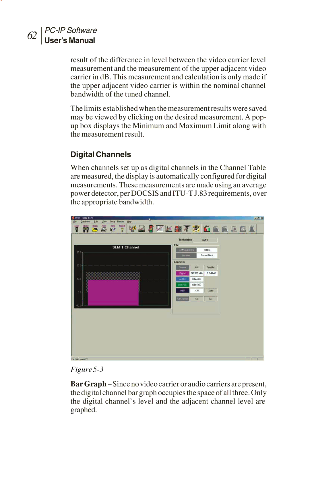
When channels set up as digital channels in the Channel Table are measured, the display is automatically configured for digital measurements. These measurements are made using an average power detector, per DOCSIS and
Figure
Bar Graph – Since no video carrier or audio carriers are present, the digital channel bar graph occupies the space of all three. Only the digital channel’s level and the adjacent channel level are graphed.