6.3 OVERALL MECHANICAL INFORMATION
6.3.1 MECHANICAL COMPNENT LAYOUT
1 | 2 | 3 | 4 | 5 |
15 |
|
|
| 6 |
|
|
|
| |
14 |
|
|
|
|
|
|
|
| 7 |
13 |
|
|
|
|
12 |
|
|
| 8 |
|
|
|
| |
11 |
|
|
| 9 |
10 |
|
|
| |
|
|
|
|
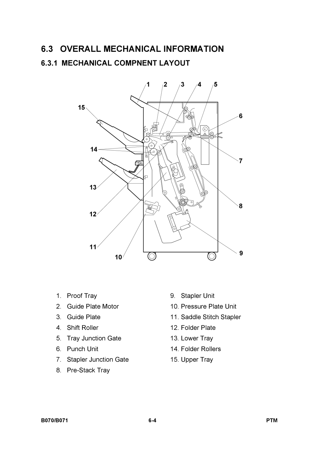
1. | Proof Tray | 9. | Stapler Unit |
2. | Guide Plate Motor | 10. | Pressure Plate Unit |
3. | Guide Plate | 11. | Saddle Stitch Stapler |
4. | Shift Roller | 12. | Folder Plate |
5. | Tray Junction Gate | 13. | Lower Tray |
6. | Punch Unit | 14. | Folder Rollers |
7. | Stapler Junction Gate | 15. | Upper Tray |
8. |
|
|
B070/B071 | PTM |