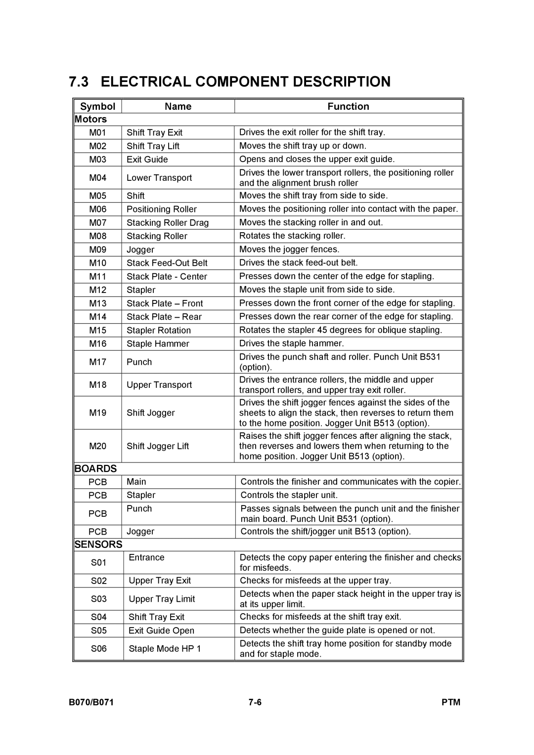
7.3 ELECTRICAL COMPONENT DESCRIPTION
Symbol |
| Name | Function | |
Motors |
|
|
| |
M01 |
| Shift Tray Exit | Drives the exit roller for the shift tray. | |
M02 |
| Shift Tray Lift | Moves the shift tray up or down. | |
M03 |
| Exit Guide | Opens and closes the upper exit guide. | |
M04 |
| Lower Transport | Drives the lower transport rollers, the positioning roller | |
| and the alignment brush roller | |||
|
|
| ||
M05 |
| Shift | Moves the shift tray from side to side. | |
M06 |
| Positioning Roller | Moves the positioning roller into contact with the paper. | |
M07 |
| Stacking Roller Drag | Moves the stacking roller in and out. | |
M08 |
| Stacking Roller | Rotates the stacking roller. | |
M09 |
| Jogger | Moves the jogger fences. | |
M10 |
| Stack | Drives the stack | |
M11 |
| Stack Plate - Center | Presses down the center of the edge for stapling. | |
M12 |
| Stapler | Moves the staple unit from side to side. | |
M13 |
| Stack Plate – Front | Presses down the front corner of the edge for stapling. | |
M14 |
| Stack Plate – Rear | Presses down the rear corner of the edge for stapling. | |
M15 |
| Stapler Rotation | Rotates the stapler 45 degrees for oblique stapling. | |
M16 |
| Staple Hammer | Drives the staple hammer. | |
M17 |
| Punch | Drives the punch shaft and roller. Punch Unit B531 | |
| (option). | |||
|
|
| ||
M18 |
| Upper Transport | Drives the entrance rollers, the middle and upper | |
| transport rollers, and upper tray exit roller. | |||
|
|
| ||
|
|
| Drives the shift jogger fences against the sides of the | |
M19 |
| Shift Jogger | sheets to align the stack, then reverses to return them | |
|
|
| to the home position. Jogger Unit B513 (option). | |
|
|
| Raises the shift jogger fences after aligning the stack, | |
M20 |
| Shift Jogger Lift | then reverses and lowers them when returning to the | |
|
|
| home position. Jogger Unit B513 (option). | |
BOARDS |
|
|
| |
PCB |
| Main | Controls the finisher and communicates with the copier. | |
PCB |
| Stapler | Controls the stapler unit. | |
PCB |
| Punch | Passes signals between the punch unit and the finisher | |
|
| main board. Punch Unit B531 (option). | ||
|
|
| ||
PCB |
| Jogger | Controls the shift/jogger unit B513 (option). | |
SENSORS |
|
|
| |
S01 | Entrance | Detects the copy paper entering the finisher and checks | ||
| for misfeeds. | |||
|
|
| ||
S02 | Upper Tray Exit | Checks for misfeeds at the upper tray. | ||
S03 | Upper Tray Limit | Detects when the paper stack height in the upper tray is | ||
at its upper limit. | ||||
|
|
| ||
S04 | Shift Tray Exit | Checks for misfeeds at the shift tray exit. | ||
S05 | Exit Guide Open | Detects whether the guide plate is opened or not. | ||
S06 | Staple Mode HP 1 | Detects the shift tray home position for standby mode | ||
and for staple mode. | ||||
|
|
| ||
|
|
|
| |
B070/B071 | PTM |