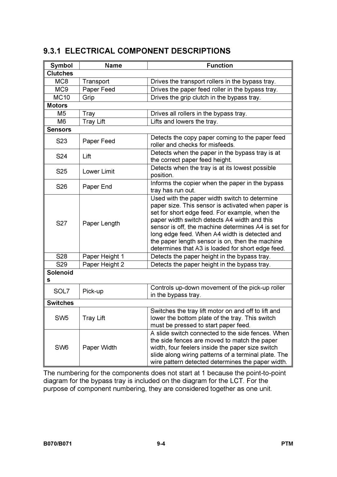
9.3.1 ELECTRICAL COMPONENT DESCRIPTIONS
Symbol | Name | Function | |
Clutches |
|
| |
MC8 | Transport | Drives the transport rollers in the bypass tray. | |
MC9 | Paper Feed | Drives the paper feed roller in the bypass tray. | |
MC10 | Grip | Drives the grip clutch in the bypass tray. | |
Motors |
|
| |
M5 | Tray | Drives all rollers in the bypass tray. | |
M6 | Tray Lift | Lifts and lowers the tray. | |
Sensors |
|
| |
S23 | Paper Feed | Detects the copy paper coming to the paper feed | |
roller and checks for misfeeds. | |||
|
| ||
S24 | Lift | Detects when the paper in the bypass tray is at | |
the correct paper feed height. | |||
|
| ||
S25 | Lower Limit | Detects when the tray is at its lowest possible | |
position. | |||
|
| ||
S26 | Paper End | Informs the copier when the paper in the bypass | |
tray has run out. | |||
|
| ||
|
| Used with the paper width switch to determine | |
|
| paper size. This sensor is activated when paper is | |
|
| set for short edge feed. For example, when the | |
S27 | Paper Length | paper width switch detects A4 width and this | |
sensor is off, the machine determines A4 is set for | |||
|
| ||
|
| long edge feed. When A4 width is detected and | |
|
| the paper length sensor is on, then the machine | |
|
| determines that A3 is loaded for short edge feed. | |
S28 | Paper Height 1 | Detects the paper height in the bypass tray. | |
S29 | Paper Height 2 | Detects the paper height in the bypass tray. | |
Solenoid |
|
| |
s |
|
| |
SOL7 | Controls | ||
in the bypass tray. | |||
|
| ||
Switches |
|
| |
|
| Switches the tray lift motor on and off to lift and | |
SW5 | Tray Lift | lower the bottom plate of the tray. This switch | |
|
| must be pressed to start paper feed. | |
|
| A slide switch connected to the side fences. When | |
|
| the side fences are moved to match the paper | |
SW6 | Paper Width | width, four feelers inside the paper size switch | |
|
| slide along wiring patterns of a terminal plate. The | |
|
| wire pattern detected determines the paper width. | |
|
|
|
The numbering for the components does not start at 1 because the
B070/B071 | PTM |