6.5.6 SHIFT MECHANISM
[A]
[B]
[C]
[D] |
[G] |
[E] |
[H] |
[I]
[F]
[K]
[J]
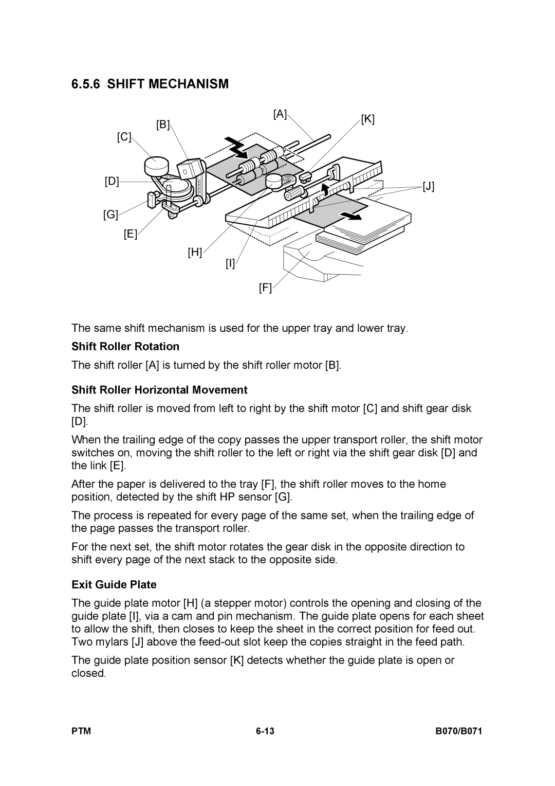
The same shift mechanism is used for the upper tray and lower tray.
Shift Roller Rotation
The shift roller [A] is turned by the shift roller motor [B].
Shift Roller Horizontal Movement
The shift roller is moved from left to right by the shift motor [C] and shift gear disk [D].
When the trailing edge of the copy passes the upper transport roller, the shift motor switches on, moving the shift roller to the left or right via the shift gear disk [D] and the link [E].
After the paper is delivered to the tray [F], the shift roller moves to the home position, detected by the shift HP sensor [G].
The process is repeated for every page of the same set, when the trailing edge of the page passes the transport roller.
For the next set, the shift motor rotates the gear disk in the opposite direction to shift every page of the next stack to the opposite side.
Exit Guide Plate
The guide plate motor [H] (a stepper motor) controls the opening and closing of the guide plate [I], via a cam and pin mechanism. The guide plate opens for each sheet to allow the shift, then closes to keep the sheet in the correct position for feed out.
Two mylars [J] above the
The guide plate position sensor [K] detects whether the guide plate is open or closed.
PTM | B070/B071 |