7.5.7 PAPER EXIT STACKING
|
| [A] |
|
| [B] |
| [E] | [C] |
[F] |
| |
|
| |
|
| [D] |
[G] | [H] | [I] |
|
|
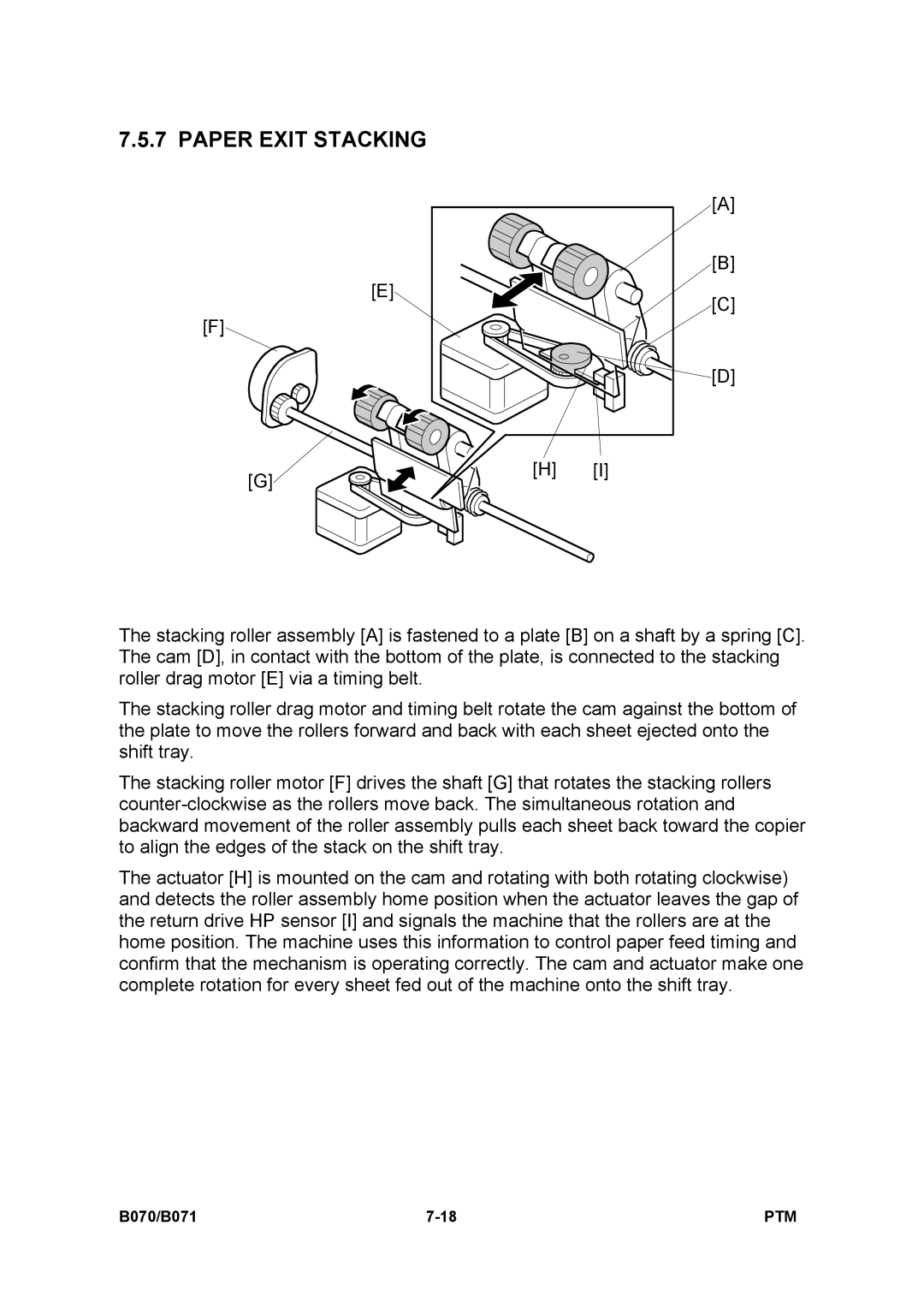
The stacking roller assembly [A] is fastened to a plate [B] on a shaft by a spring [C]. The cam [D], in contact with the bottom of the plate, is connected to the stacking roller drag motor [E] via a timing belt.
The stacking roller drag motor and timing belt rotate the cam against the bottom of the plate to move the rollers forward and back with each sheet ejected onto the shift tray.
The stacking roller motor [F] drives the shaft [G] that rotates the stacking rollers
The actuator [H] is mounted on the cam and rotating with both rotating clockwise) and detects the roller assembly home position when the actuator leaves the gap of the return drive HP sensor [I] and signals the machine that the rollers are at the home position. The machine uses this information to control paper feed timing and confirm that the mechanism is operating correctly. The cam and actuator make one complete rotation for every sheet fed out of the machine onto the shift tray.
B070/B071 | PTM |