2.6.2 DEVELOPMENT MECHANISM
[E] | [F] |
[C] |
|
[H]
[G]
![]()
![]()
![]() [A]
[A]
[D]
[B]
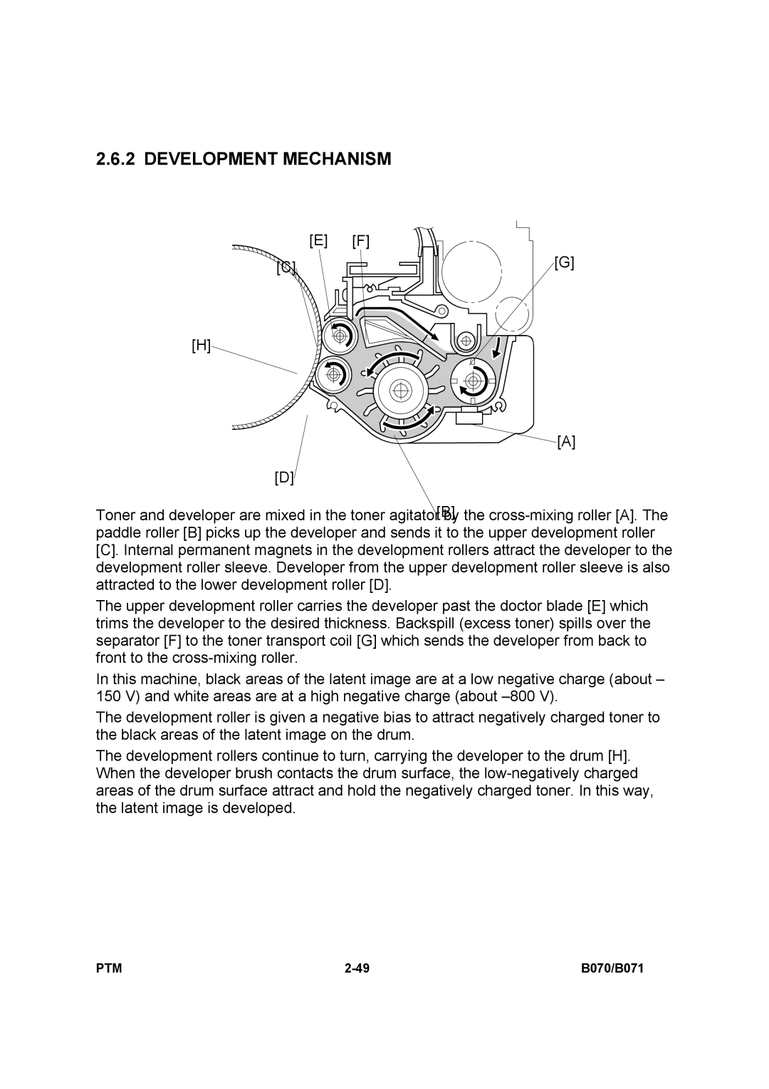
Toner and developer are mixed in the toner agitator by the
[C].Internal permanent magnets in the development rollers attract the developer to the development roller sleeve. Developer from the upper development roller sleeve is also attracted to the lower development roller [D].
The upper development roller carries the developer past the doctor blade [E] which trims the developer to the desired thickness. Backspill (excess toner) spills over the separator [F] to the toner transport coil [G] which sends the developer from back to front to the
In this machine, black areas of the latent image are at a low negative charge (about – 150 V) and white areas are at a high negative charge (about
The development roller is given a negative bias to attract negatively charged toner to the black areas of the latent image on the drum.
The development rollers continue to turn, carrying the developer to the drum [H]. When the developer brush contacts the drum surface, the
PTM | B070/B071 |