MJ-1103/1104
Trademarks
Page
Page
Contents
Paper jam in movable tray section
Saddle Stitch Finisher stapler related error MJ-1104
Specifications
SPECIFICATIONS, Accessory and Consumables
Stacking Type Facedown Stacking Height with Stationary Tray
Finisher section Common for MJ-1103/1104
Paper Size
Height
Paper Size
A4, B5, LT, 8.5SQ, 16K A3, A4-R, B4, FOLIO, LD, LG, LT-R
Thick paper cover included
Saddle stitch section MJ-1104
64 80g/m 2 Paper 81 90g/m 2 Paper 91 105g/m 2 Paper
91 105g/m2 Paper
Accessory
Consumables
MJ-1103 MJ-1104
Main Components
General Description
Units
Sectional View
Finisher section B-1 Front side view
Paper exit guide clutch
Gate solenoid
Rear side view
Saddle section C-1 Front side view
M14
M16 M17
Transport roller
Paper holding damper
Electric Parts Layout
M13
SOL2 M10 CLT2 M12 M2
S19
S20
Symbols and Functions of Various Components
Symbol Name Function Remarks
Motors Saddle section MJ-1104
Electromagnetic spring clutches Saddle section MJ-1104
Solenoids Finisher section Common for MJ-1103/1104
Solenoids Saddle section MJ-1104
P11-I20 7 Fig For the stapling operation
Stapler home position sensor
Sensors and switches Saddle section MJ-1104
PC board Finisher section Common for MJ-1103/1104
PC board Saddle section MJ-1104
Finisher section
Diagram of Signal Blocks
ROM
Saddle section
Equipment connection switch Connected 24V power supplied
Description of Interface Signals
Sent data transmitted from the Equipment to the Finisher
Equipment TxD Converter RxD Finisher PC board
General Description
Basic Operations
Description of Operations
Fold unit Stacker EFS unit Saddle tray
Junction box Side alignment Unit
Junction box paper detection sensor
Junction Box
Simple Stack Mode
Finisher paper feeding section
Gate flap Entrance roller Gate solenoid
Stationary Tray roller Entrance sensor Exit motor
Paper exit to the stationary tray
Paper exit to the movable tray
Movable tray position
Operation of Movable Tray
Position-C sensor
Paper transport section
Job offset stack mode / Staple stack mode
Paper pusher home position sensor
Mulch-active drop mechanism section
Paper pushing arm motor
Paper pushing plate Catching pad
Description of Operations
Bundle Job Offset Operation
Stapler interference switch
Stapling Operation
Stapler interference
Paper exiting operation
Stack transport roller-2 Paper exit belt
Clutch
Saddle stitch feeding section
Operation in the saddle stitch section
Side alignment
Stack transport
Stapling
Paper holding
Folding
Exit transport sensor Folding roller
Folding motor encoder sensor
Additional folding / exiting
Simple stack mode
Flow Chart
Exit motor on
Transport sensor ON?
Bundle job offset mode/ stapling stack mode
Entrance motor on
Center-binding mode
Feeding Sensor ON?
Saddle transport motor on
Finishier section
Description Of Circuit
Buffer roller drive circuit
Motor rotation Remarks
By the paper pushing plate
Paper pushing arm motor drive circuit
Buffer tray guide motor drive circuit
Guide is closed
Guide is opened
Front alignment plate is closed
Front / rear alignment motor drive circuit
Front alignment plate is opened
Rear alignment plate is closed
Stack transport motor drive circuit
Paper is pulled
Entrance motor drive circuit
Exit motor drive circuit
Paper is transported to the stationary tray
Or buffer tray
Stapler unit shift motor drive circuit
Stapler unit is shifted to the front side
Stapler unit is shifted to the rear side
Transport motor drive circuit
Paper is transported to the finishing posi
Tion
Paper is pulled into the finishing position
Paddle motor drive circuit
Then pushed off
Eliminates backlash
Movable tray unit is shifted to the lower side
Movable tray shift motor drive circuit
Movable tray unit is shifted to the upper side
Stop
Recovery operation
Reset circuit
Stapler motor drive circuit
IC22
Stacker motor drive circuit
Saddle section
Stacker is moved to the stapling
Position
Paper is aligned to fix their side
Side alignment motor drive circuit
Ways deviation with a jog moved
Open the jog
Only when the stapler operates abnormally
Front / Rear saddle stapler motor drive circuit
Initial operation
Paper is transported
Saddle transport motor drive circuit
At a transport speed lower than 200 mm
At a transport speed 400 mm/s or higher
Operates the folding
Folding motor drive circuit
Paper is exited to the saddle tray
Stop Not used
Operates the additional folding
Additional folding motor drive circuit
Stationary tray
Covers
Saddle tray
Movable tray
Movable tray
Leveling arm
Control panel unit
Connector
Remove 1 screw on the upper side of the front rail cover
Saddle tray
Front cover
Front upper cover MJ-1104
Front lower cover MJ-1104
Front lower cover
Handle cover / Cover lock bracket
Access cover
Rear cover
Finisher cable
Saddle access cover
Right upper cover
Relay guide / Feeding discharge brush / Right cover
Remove 3 screws, and then take off the left upper cover
Left upper cover
Clamp
Hook
Take off the movable tray. P.4-2 B Movable tray
Front rail cover / Rear rail cover
Front rail
Cover
Grate-shaped guide
Connector
Relay
Shutter Hook
Grate-shaped
Left lower cover Left lower cover MJ-1103
Guide
Clamp Harness
Front foot cover / Rear foot cover
Left lower cover MJ-1104
Cover
Front foot cover
Junction box unit
Units Finisher section
Clamp
If board
Belt
Disconnect the connector of the front cover switch
Buffer unit
Rear rail guide
Entrance motor
Remove 4 screws, and then take off the buffer unit
Buffer unit
Paper pusher plate Buffer guide
Disconnect the connector of the buffer tray guide motor
Connector Buffer tray guide motor
Buffer unit-1
Take off the belt of the buffer roller drive motor
Relay Connector Cramp
Finishing tray unit
Plate
Buffer unit-1
Clip
Bushing
Belt
Spring
Belt Pin Bushing Clips Transport roller pulley-3
Flexible cable
Stapler
Protrusion
Staple carrier
Movable tray shift motor unit
Sensor rail
Sensor rail
Measure
Bracket
Bushing
Shift motor unit
Saddle unit
Units Saddle section MJ-1104
SDL board
Table beneath
Shaft
Frame
Support
Switchback unit
Paper holding unit
Rear bracket Support Bracket Front bracket
Paper holding unit
Saddle stapler unit
Side alignment unit
Install the jig on the hole of the lower sta Pler frame
Pler frame assembly
Remove 4 screws and take off the upper sta
Upper stapler
Front saddle stapler
Fold plate
Mylar
Folding drive unit
Binding wire
Remove one clip and then remove the bush Ing
Bushing Clip
Pin Pulley
Remove one clip and then remove the pulley and pin
Spring Folding drive unit
Scale Mark Gear bracket
Relay connector
Wire
EFS unit
Clanp
Access lever
Rear bracket
EFS jam
Stacker unit
Stacker unit
Feeding roller
Rollers Finisher section
Board
Front bracket Junction box upper Transport guide
Jam access lever
Remove one screw, and then sensor bracket of feeding sensor
Sensor
Knob
Junction roller
Pulley
Pin Gear
Clip
Remove 3 screws, and then take off the transport guide
Junction roller
Screw
Take off the arm by pulling it out upward
Arm
Catching pad Arm Arm linkage portion
Front pull-in guide
Rear alignment plate
Rear finishing tray cover
Jig Rear pull-in guide
Rear Pull-in guide Front
Paddle shaft
Front transport roller / Rear transport roller
Rear transport roller
Entrance roller
Front transport roller
Pulley Bushing Rear transport roller
Then take off the entrance roller
Remove 1 E-ring, and then slide 1 bushing
Remove 1 E-ring. Then remove 1 pulley
Bushing and 1 pin from the entrance roller
Rear finishing tray cover
Stack transport roller-1
Stack transport roller-2
Buffer tray guide motor
Buffer roller
Remove 2 screws, and then take off the rear side frame
Buffer roller drive motor
Rear side
Front buffer roller guide
Buffer roller
Rear buffer roller guide
Take off the lift guide from the buffer roller
Spacer
Lift guide
Tions where the gap between the trailing
When installing the front and rear stationary
Upper exit roller / Upper exit roller guide
Tray transport guides, fix them at the posi
Remove 5 E-rings, 1 gear, 1 pin, 1 actuator and 2 bushings
Remove 4 screws of the upper exit roller guide
Upper exit roller guide
Upper exit roller
Feed knob Bushing Assembly Belt
Switchback transport roller
Switchback
Rollers Saddle section MJ-1104
Belt
Assisting roller
Ejecting roller
Clip Bushing
Spring
Remove the 2 springs
Bushing Pin
Ejecting roller Bushing Arm
Upper folding roller / Lower folding roller
Remove 2 E-rings and take off the 2 bearing
Bearing
Jam release lever Upper folding roller
Remove 1 E-rings and take off the gear and pin
Pin
Bearing
Jam release lever Lower folding roller
Exit roller
Lower transport guide
Clip Bushing Exit roller
Entrance motor M1
Motor Finisher section
Remove 2 screws, and then remove the motor damper
Buffer tray guide motor M2
Buffer roller drive motorM4
Paddle motor M3
Front alignment motor M5
Front alignment motor Clamp Relay connector
Rear alignment motor M6
Transport motor M7
Shaft Gear Pin
Stack transport motor M8
Stapler unit shift motor M9
Remove 2 screws and then take off the bracket
Paper pusher arm motorM10
Relay Connector Clamp
Shift motor
Take off the stationary tray. P.4-1 a Stationary tray
Assembly
Exit motor M11
Exit motor
Movable tray shift motor
Sensor rail
Movable tray shift motor
Stacker motor M14
Motor Saddle section MJ-1104
Stacker
Motor bracket Gear
Upper safety cover
Side alignment motor M15
Stacker Motor Clamp
Saddle transport motor M16
Remove 2 screws, and then take off the motor bracket
Motor bracket
Folding motor M17
Take off the belt of folding motor
Remove 2 screws and take off the folding motor
Additional folding motor M20
Clamp Binding wire
Solenoid
Shutter clutch CLT1
Paper exit guide clutch CLT2
Protection
Folding blade clutch CLT3
Paper holding clutch CLT4 MJ-1104
Catching solenoid SOL1
Take off the junction box unit P.4-13 a Junction box unit
Buffer roller lift solenoid SOL2 / Patting solenoid SOL3
Remove 2 screws, and then take off the catching solenoid
Solenoid sensor unit
Damper
Buffer roller lift solenoid Patting solenoid
Gate solenoid SOL4
Remove 3 screws, and then take off Remove the spring
Scale Bracket
Remove 2 screws, and then take off the gate solenoid
Transport path switching solenoid SOL5 MJ-1104
Bracket Gate flap
Shaft of the entrance roller
Belt
Binding wire
Arm Transport path switching solenoid Surface
Assisting roller solenoid SOL6 MJ-1104
Stacker guide
Relay
Entrance sensor S1
Sensors / Switches Finisher section
Release the latch, and then take off the entrance sensor
Transport sensor S2
Release the latch, and then take off the transport sensor
Paddle home position sensor S3
FIN board bracket
Buffer tray home position sensor S5
Shutter opening / closing sensor S4
Shutter opening
Closing sensor
Buffer tray home position sensor
Front alignment plate home position sensor S7
Paper pusher home position sensor S6
Paper pusher cam
Paper pusher plate
Stack exit belt home position sensor S9
Rear alignment plate home position sensor S8
Rear alignment
Plate home position sensor
Take off the belt from the stack transport motor
Stapler unit home position sensor S10
Stapler interference sensor S11 / Actuator
Stack exit belt Home position sensor
Finishing tray paper detection sensor S12
Remove the clip, and then take off the sta- pler base frame
Take off the finishing unit P.4-19 D Finishing tray unit
Remove 3 screws, and then take off the front
Front alignment plate guide
Sensor rail
Movable tray paper-full sensor S16
Movable tray paper exist sensor S17
Stationary tray paper-full sensor S18
Spacer Actuator Stationary tray paper-full sensor
Feeding sensor S22
Movable tray shift motor sensor S23
Release the latch, and then take off the feed- ing sensor
Feeding sensor
Movable tray shift motor sensor
Remove 2 screws, and then take off the front cover switch
Front cover switch SW1
Connection sensor S25
Connection sensor
Spring Belt tension arm
Stationary tray opening/closing switch SW2
Remove 4 screws, and then take off the switch bracket
Stapler interference switch SW3
Switch bracket
Remove 4 screws, and then take off the upper saddle cover
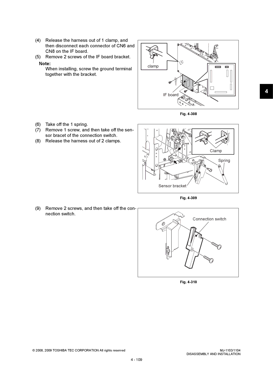
Connection switch SW4
Remark
Upper saddle cover
Connection switch
Remove 2 screws, and then take off the con Nection switch
Sensors / Switches Saddle section MJ-1104
Junction box paper detection sensor S26
Transport path-2 sensor S27
Transport path-3 sensor S28
Ejecting roller sensor S29
Stacker paper detection sensor
Stacker paper detection sensor S30
Release the latch, and then take off the exit sensor
Exit sensor S31
Saddle tray paper detection sensor S32
Exit sensor
Folding motor encoder sensor S34
Stacker home position sensor S33
Stacker guide
Folding motor
Side alignment home position sensor S36
Folding blade home position sensor S35
Additional folding home position sensor S39
Paper holding home position sensor S38
Folding carrier to the center
Sensor bracket
Additional folding motor encoder sensor S42
Exit transport sensor S41
Exit transport sensor
Additional folding motor encoder sensor
Connector and take off the sensor bracket
Saddle unit opening/closing switch SW5
Saddle unit opening/closing switch
Remove 2 screws, and then disconnect
PC Boards / Discharge Brush
Finisher control PC board FIN board
Remove 4 screws, and then take off the FIN board
Remove 4 screws, and then take off the I/F board
Interface PC board I/F board
Saddle control PC board SDL board
Discharge brush
Front stationary tray
Mylar
Rear stationary tray
Since the insertion of the screwdriver has
Procedure for lowering the movable tray
Released the driving gear of the movable tray
Stationary tray
Adjusting for A4 size paper Adjusting for LT size paper
Adjusting the Alignment Position
B5 paper Vertical Adjustment sheet
Remarks
Button1 Button2
Number of Blinking Adjustment Value
Adjusting the Stapling Position
LED3 LED2
Sample
Stapling/folding position adjustment in saddle unit
Phenomenon Contents Adjustment
Folding position adjustment
Number of blinking Adjustment value
Stapling position adjustment
Number of blinking Adjustment value
Saddle Stitch Skew Adjustment
EA10 Transport delay jam paper not inserted
Paper Transport Jam
Paper jam in entrance section
CB10 Entrance motor M1 abnormality
EA60 Early arrival jam
EA20 Paper transport jam in Finisher entrance sensor
Paper jam in buffer unit-1
Troubleshooting
EA28 Paper transport jam in Finisher paper holding delay
Paper jam in buffer unit-2
EA31 Transport path paper remaining jam in Finisher
ED16 Buffer tray home position error
Paper jam in finishing tray section
CB12 Buffer roller drive motor M4 abnormality
CB14 Paper pusher arm motor M10 abnormality
ED14 Rear alignment plate home position error
ED13 Front alignment plate home position error
ED15 Paddle home position error
EA70 Stack exit belt home position error
EA32 Exit paper remaining jam
CC41 Paper pusher cam home position abnormality
ED12 Shutter home position error
CB31 Movable tray paper-full detection error
Paper jam in movable tray section
CB30 Movable tray shift motor M12 abnormality
EA40 Cover open error
EA90 Saddle unit open error MJ-1104
Cover open jam
Troubleshooting
Paper jam in Saddle Stitch Finisher transport section
Paper Transport Jam in Saddle Stitch Section MJ-1104
EAA0
Paper remaining in Saddle Stitch Finisher
Paper transport jam in Saddle Stitch Finisher
EAB0
EAB1
EF14 Saddle exit jam
Short paper jam in Saddle Stitch Finisher
EF13 Saddle unit paper holding home position detection error
Paper jam in side alignment section
Paper jam in stack transport section
EF20 Saddle stacker jam
Troubleshooting
EF19 Saddle Stitch Finisher paper folding jam
Paper jam in folding section
Paper jam in additional folding section
Stapler related error
Other Errors
EA50
Stapling jam
CB60 Stapler unit shift motor M9 abnormality
CB51 Stapler shift home position error
EF11 Front saddle staple error
Saddle Stitch Finisher stapler related error MJ-1104
EF12 Rear saddle staple error
CBA0 Front saddle stapler home position error
Communication Related Error
CBB0 Rear saddle stapler home position error
When MJ-6102 is connected
Memory error
CB91 Saddle flash ROM abnormality
CB81 Flash ROM abnormality
Front side Rear side
Maintenance and Inspection Points
Preventive Maintenance Checklist
Symbols used in the checklist
Cleaning Lubrication/Coating Replacement Operation check
Items to check Cleaning Lubrication Replacement Operation
Buffer tray shaft
Finishing tray shaft Rack gear
EFS carrier shaft
Update of CNV board
Firmware Update
Connector Mark for ROM
Installation direction
Download jig
Update of FIN board
Preventive Maintenance PM / Firmware Update
Download jig
Update of SDL board
Preventive Maintenance PM / Firmware Update
Preventive Maintenance PM / Firmware Update
Finisher control PC board
Harness Diagram
Electric Circuit
Interface PC board
Saddle control PC board
Opening/closing switch
Finisher control PC board 1. Circuit Diagram
Circuit Diagram
Circuit Diagram
Circuit Diagram
Circuit Diagram
Circuit Diagram
Circuit Diagram
Circuit Diagram
Circuit Diagram
Circuit Diagram
Circuit Diagram
Circuit Diagram
Circuit Diagram
Interface PC board 1. Circuit Diagram
Circuit Diagram
Saddle control PC board 1. Circuit Diagram
2008, 2009 Toshiba TEC Corporation All rights reserved
Circuit Diagram
2008, 2009 Toshiba TEC Corporation All rights reserved
Circuit Diagram
2008, 2009 Toshiba TEC Corporation All rights reserved
Circuit Diagram
Circuit Diagram
Circuit Diagram
Circuit Diagram
Circuit Diagram
Circuit Diagram
Electric Circuit
Finisher controller PC board Interface PC board
PC board
Saddle control PC board
Electric Circuit
Ver.03
Ver.02
Ver.01
Revision Record