Unit Description
2.2. Back Panel
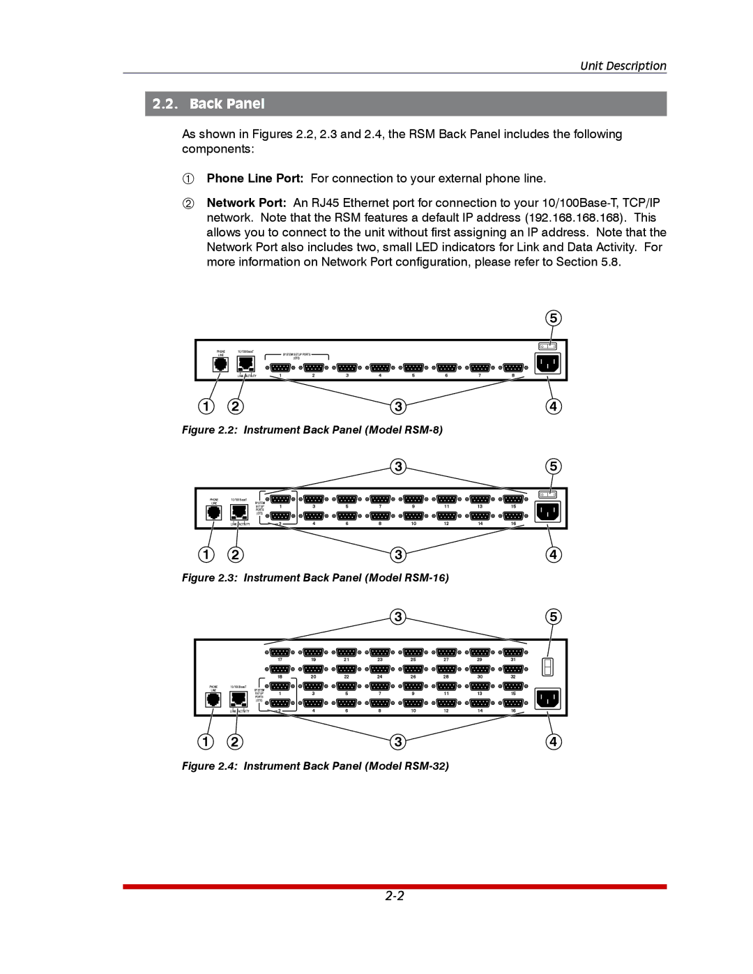
As shown in Figures 2.2, 2.3 and 2.4, the RSM Back Panel includes the following components:
Phone Line Port: For connection to your external phone line.
Network Port: An RJ45 Ethernet port for connection to your
|
|
|
|
|
|
|
|
|
| 5 |
|
|
|
|
|
|
|
|
| O | I |
PHONE | 10/100BaseT |
| SYSTEM SETUP PORTS |
|
|
|
|
|
|
|
LINE |
|
|
|
|
|
|
|
|
| |
|
|
| (DTE) |
|
|
|
|
|
|
|
| LINK ACTIVITY | 1 | 2 | 3 | 4 | 5 | 6 | 7 | 8 |
|
1 | 2 |
|
|
|
| 3 |
|
|
| 4 |
Figure 2.2: Instrument Back Panel (Model |
|
|
|
| ||||||
|
|
|
|
|
| 3 |
|
|
| 5 |
|
|
|
|
|
|
|
|
| O | I |
PHONE | 10/100BaseT |
|
|
|
|
|
|
|
|
|
LINE | SYSTEM | 1 | 3 | 5 | 7 | 9 | 11 | 13 | 15 |
|
| SETUP |
| ||||||||
| PORTS |
|
|
|
|
|
|
|
|
|
| (DTE) |
|
|
|
|
|
|
|
|
|
| LINK ACTIVITY | 2 | 4 | 6 | 8 | 10 | 12 | 14 | 16 |
|
1 | 2 |
|
|
|
| 3 |
|
|
| 4 |
Figure 2.3: Instrument Back Panel (Model |
|
|
| |||||||
|
|
|
|
|
| 3 |
|
|
| 5 |
|
| 17 | 19 | 21 | 23 | 25 | 27 | 29 | 31 |
|
|
| 18 | 20 | 22 | 24 | 26 | 28 | 30 | 32 |
|
PHONE | 10/100BaseT |
|
|
|
|
|
|
|
|
|
LINE | SYSTEM | 1 | 3 | 5 | 7 | 9 | 11 | 13 | 15 |
|
| SETUP |
| ||||||||
| PORTS |
|
|
|
|
|
|
|
|
|
| (DTE) |
|
|
|
|
|
|
|
|
|
| LINK ACTIVITY | 2 | 4 | 6 | 8 | 10 | 12 | 14 | 16 |
|
1 | 2 |
|
|
|
| 3 |
|
|
| 4 |