TOP BURNER IGNITOR SYSTEM
Description
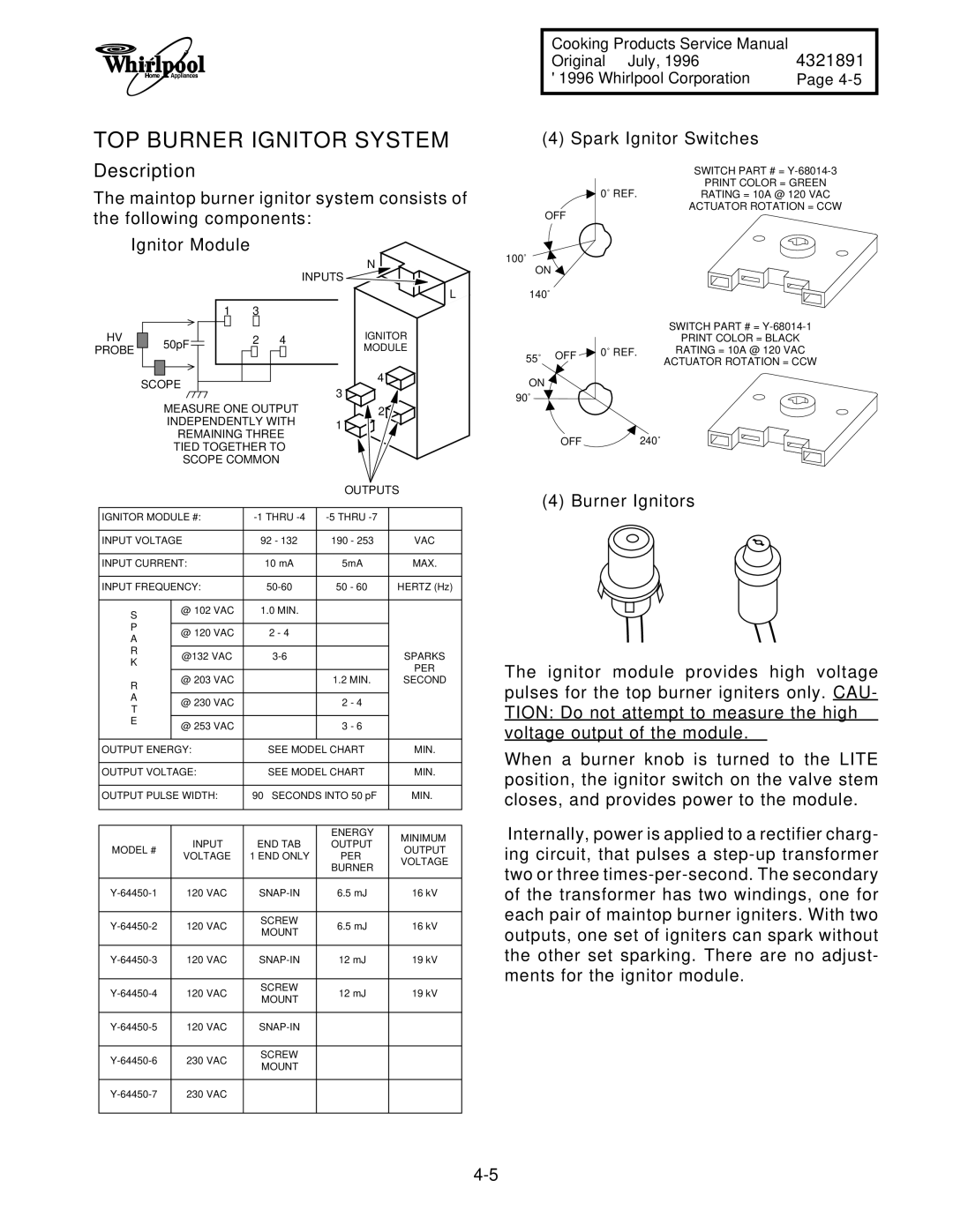
The maintop burner ignitor system consists of the following components:
Ignitor Module
|
|
|
|
|
|
|
|
|
|
|
|
|
|
|
|
|
| N |
|
|
|
|
|
|
|
|
|
|
|
|
|
|
|
|
| INPUTS |
| ||
|
|
|
|
|
|
|
|
|
|
|
|
|
|
|
|
|
|
| L |
|
|
|
|
|
|
| 1 | 3 |
|
|
|
|
| ||||||
| HV |
|
|
|
|
|
|
|
|
|
|
|
|
|
|
|
| IGNITOR | |
|
|
| 50pF |
|
|
| 2 4 |
| |||||||||||
|
|
|
|
| |||||||||||||||
|
|
|
|
|
|
|
|
|
|
|
|
|
|
|
| MODULE | |||
PROBE |
|
|
|
|
|
|
|
|
|
|
| ||||||||
|
|
|
|
|
|
|
|
|
|
|
|
| |||||||
|
|
|
|
|
|
|
|
|
|
|
|
|
|
|
|
|
|
|
|
|
|
|
|
|
|
|
|
|
|
|
|
|
|
|
|
| 4 |
| |
|
| SCOPE |
|
|
|
|
|
|
|
| |||||||||
|
|
|
|
|
|
|
|
| 3 |
| |||||||||
|
|
|
|
|
|
|
|
|
|
|
|
|
|
|
|
|
| ||
|
|
|
|
| MEASURE ONE OUTPUT | 2 |
| ||||||||||||
|
|
|
|
| INDEPENDENTLY WITH | 1 |
| ||||||||||||
|
|
|
|
|
| REMAINING THREE |
| ||||||||||||
|
|
|
|
|
|
|
|
| |||||||||||
|
|
|
|
|
| TIED TOGETHER TO |
|
|
| ||||||||||
|
|
|
|
|
| SCOPE COMMON |
|
|
| ||||||||||
|
|
|
|
|
|
|
|
|
|
|
|
|
|
|
|
|
| OUTPUTS | |
|
|
|
|
|
|
|
| ||||||||||||
| IGNITOR MODULE #: |
|
|
| |||||||||||||||
|
|
|
|
|
| ||||||||||||||
| INPUT VOLTAGE | 92 - 132 | 190 - 253 | VAC | |||||||||||||||
|
|
|
|
|
|
|
|
|
|
| |||||||||
| INPUT CURRENT: |
|
|
|
| 10 mA |
| 5mA | MAX. | ||||||||||
|
|
|
|
|
| ||||||||||||||
| INPUT FREQUENCY: | 50 - 60 | HERTZ (Hz) | ||||||||||||||||
|
|
|
|
|
|
|
|
|
|
|
|
|
|
| |||||
| S |
| @ 102 VAC |
|
|
|
| 1.0 MIN. |
|
|
| ||||||||
|
|
|
|
|
|
|
|
|
|
|
|
|
|
|
| ||||
| P |
|
|
|
|
|
|
|
|
|
|
|
|
|
|
| |||
|
| @ 120 VAC | 2 - 4 |
|
|
| |||||||||||||
| A |
|
|
|
| ||||||||||||||
|
|
|
|
|
|
|
|
|
|
|
|
|
|
|
| ||||
| R |
| @132 VAC |
|
| SPARKS | |||||||||||||
| K |
|
|
| |||||||||||||||
|
|
|
|
|
|
|
|
|
|
|
|
|
|
| PER | ||||
|
|
|
|
|
| @ 203 VAC |
|
|
|
|
|
|
| 1.2 MIN. | |||||
| R |
|
|
|
|
|
|
|
| SECOND | |||||||||
|
|
|
|
|
|
|
|
|
|
|
|
|
|
|
| ||||
| A |
| @ 230 VAC |
|
|
|
|
|
|
| 2 - 4 |
| |||||||
| T |
|
|
|
|
|
|
|
|
| |||||||||
|
|
|
|
|
|
|
|
|
|
|
|
|
|
|
| ||||
| E |
| @ 253 VAC |
|
|
|
|
|
|
| 3 - 6 |
| |||||||
|
|
|
|
|
|
|
|
|
|
|
|
|
| ||||||
|
|
|
|
|
|
|
|
|
| ||||||||||
| OUTPUT ENERGY: |
|
|
|
| SEE MODEL CHART | MIN. | ||||||||||||
|
|
|
|
|
|
|
| ||||||||||||
| OUTPUT VOLTAGE: |
|
|
|
| SEE MODEL CHART | MIN. | ||||||||||||
|
|
|
|
| |||||||||||||||
| OUTPUT PULSE WIDTH: |
| 90 µ SECONDS INTO 50 pF | MIN. | |||||||||||||||
|
|
|
|
|
|
|
|
|
|
|
|
|
|
|
|
|
|
| |
|
|
|
|
|
|
|
|
|
|
|
|
|
|
|
|
|
|
| |
|
|
|
|
|
|
|
|
|
|
|
|
|
|
|
|
| ENERGY | MINIMUM | |
|
|
|
|
|
| INPUT |
|
|
| END TAB | OUTPUT | ||||||||
| MODEL # |
|
|
|
| OUTPUT | |||||||||||||
|
| VOLTAGE | 1 END ONLY |
| PER | ||||||||||||||
|
|
|
|
|
|
| VOLTAGE | ||||||||||||
|
|
|
|
|
|
|
|
|
|
|
|
|
|
|
|
| BURNER | ||
|
|
|
|
|
|
|
|
|
|
|
|
|
|
|
|
|
| ||
|
|
|
|
|
|
|
|
|
| ||||||||||
|
| 120 VAC |
|
|
| 6.5 mJ | 16 kV | ||||||||||||
|
|
|
|
|
|
|
|
|
|
|
|
|
|
|
|
|
| ||
|
| 120 VAC |
|
|
|
| SCREW | 6.5 mJ | 16 kV | ||||||||||
|
|
|
|
|
| MOUNT | |||||||||||||
|
|
|
|
|
|
|
|
|
|
|
|
|
|
|
|
| |||
|
|
|
|
|
|
|
|
|
|
| |||||||||
|
| 120 VAC |
|
|
|
| 12 mJ | 19 kV | |||||||||||
|
|
|
|
|
|
|
|
|
|
|
|
|
|
|
|
|
| ||
|
| 120 VAC |
|
|
|
| SCREW |
| 12 mJ | 19 kV | |||||||||
|
|
|
|
|
| MOUNT |
| ||||||||||||
|
|
|
|
|
|
|
|
|
|
|
|
|
|
|
|
| |||
|
|
|
|
|
|
|
|
|
|
| |||||||||
|
| 120 VAC |
|
|
|
|
|
| |||||||||||
|
|
|
|
|
|
|
|
|
|
|
|
|
|
|
|
|
| ||
|
| 230 VAC |
|
|
|
| SCREW |
|
|
| |||||||||
|
|
|
|
|
| MOUNT |
|
|
| ||||||||||
|
|
|
|
|
|
|
|
|
|
|
|
|
|
|
|
| |||
|
|
|
|
|
|
|
|
|
|
|
|
|
| ||||||
|
| 230 VAC |
|
|
|
|
|
|
|
|
|
| |||||||
|
|
|
|
|
|
|
|
|
|
|
|
|
|
|
|
|
|
|
|
Cooking Products Service Manual
Original July, 1996 | 4321891 |
© 1996 Whirlpool Corporation | Page |
(4) Spark Ignitor Switches
SWITCH PART # =
PRINT COLOR = GREEN
![]() 0˚ REF.RATING = 10A @ 120 VAC
0˚ REF.RATING = 10A @ 120 VAC
ACTUATOR ROTATION = CCW
OFF |
|
|
100˚ |
|
|
ON |
|
|
140˚ |
|
|
|
| SWITCH PART # = |
|
| PRINT COLOR = BLACK |
55˚ OFF | 0˚ REF. | RATING = 10A @ 120 VAC |
| ACTUATOR ROTATION = CCW | |
|
| |
ON |
|
|
90˚ |
|
|
OFF |
| 240˚ |
(4) Burner Ignitors
The ignitor module provides high voltage pulses for the top burner igniters only. CAU-
TION: Do not attempt to measure the high voltage output of the module.
When a burner knob is turned to the LITE position, the ignitor switch on the valve stem closes, and provides power to the module.
Internally, power is applied to a rectifier charg- ing circuit, that pulses a