![]() WARNING
WARNING
Fire Hazard
pressure regulator
When you make gas line connections, espe- cially to the pressure regulator, do not make the connections too tight. If you do, you may crack the regulator (or pipe) and cause a gas leak, which could result in a possible fire, or explosion.
INSTALLING THE GAS LINE
The following procedure is for a typical gas line installation and its associated components to the gas range. Use
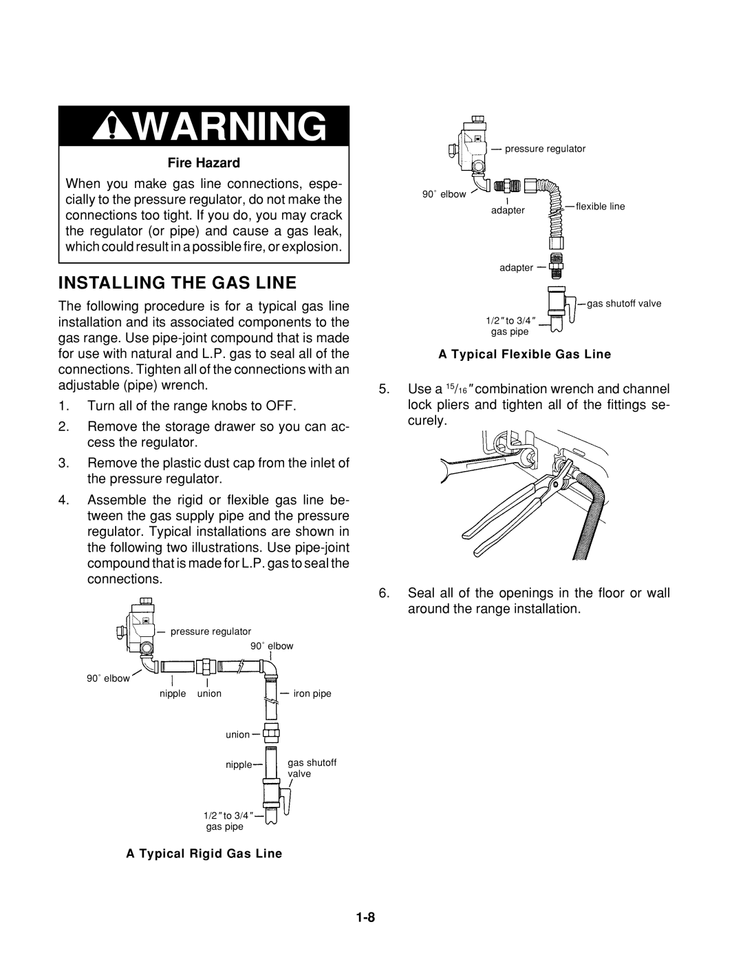
90˚ elbow
adapter
adapter
1/2" to 3/4"
gas pipe
flexible line
gas shutoff valve
for use with natural and L.P. gas to seal all of the connections. Tighten all of the connections with an adjustable (pipe) wrench.
1.Turn all of the range knobs to OFF.
2.Remove the storage drawer so you can ac- cess the regulator.
3.Remove the plastic dust cap from the inlet of the pressure regulator.
4.Assemble the rigid or flexible gas line be- tween the gas supply pipe and the pressure regulator. Typical installations are shown in the following two illustrations. Use
pressure regulator
90˚ elbow | |
90˚ elbow |
|
nipple union | iron pipe |
union |
|
nipple | gas shutoff |
| valve |
1/2" to 3/4" gas pipe
A Typical Rigid Gas Line
A Typical Flexible Gas Line
5.Use a 15/16" combination wrench and channel lock pliers and tighten all of the fittings se- curely.
6.Seal all of the openings in the floor or wall around the range installation.