Xanbus Automatic Generator Start Installation
To install the AGS using the wiring harness:
1.Connect each wire on the harness to its intended wire or contact on the generator, thermostats, or external switches. Tape, or otherwise secure, the unused wires to ensure they do not make unintended connections.
2.Plug the harness into the connector on the bottom panel of the AGS.
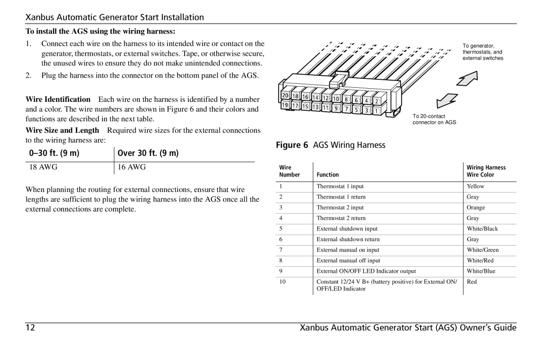
Wire Identification Each wire on the harness is identified by a number and a color. The wire numbers are shown in Figure 6 and their colors and functions are described in the next table.
Wire Size and Length Required wire sizes for the external connections to the wiring harness are:
| Over 30 ft. (9 m) |
|
|
18 AWG | 16 AWG |
|
|
When planning the routing for external connections, ensure that wire lengths are sufficient to plug the wiring harness into the AGS once all the external connections are complete.
To generator, thermostats, and external switches
To
Figure 6 AGS Wiring Harness
Wire |
| Wiring Harness |
Number | Function | Wire Color |
|
|
|
1 | Thermostat 1 input | Yellow |
2 | Thermostat 1 return | Gray |
3 | Thermostat 2 input | Orange |
4 | Thermostat 2 return | Gray |
5 | External shutdown input | White/Black |
6 | External shutdown return | Gray |
7 | External manual on input | White/Green |
8 | External manual off input | White/Red |
9 | External ON/OFF LED Indicator output | White/Blue |
10 | Constant 12/24 V B+ (battery positive) for External ON/ | Red |
| OFF/LED Indicator |
|
|
|
|
12 | Xanbus Automatic Generator Start (AGS) Owner’s Guide |