Xanbus Automatic Generator Start Installation
Wiring to the 20-contact Connector
ELECTRICAL SHOCK HAZARD
All installation wiring should be performed by a qualified installer or electrician.
The
Failure to follow these instructions can result in death or serious injury.
ELV Circuits ELV
voltage of not more than 30 Vrms or 42.2 VDC or peak, and are therefore not a shock hazard.
Class 2 Circuits As per the US National Electrical Code (NEC) and the Canadian Electrical Code (CEC), available power in Class 2 circuits is limited to 100 VA, usually by current limiting by means of overcurrent protection or series resistance. The current is limited to 5 A for circuits with
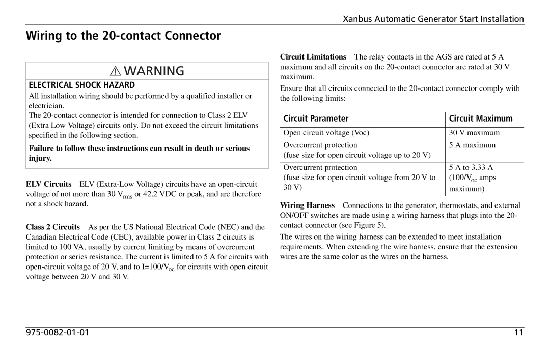
Circuit Limitations The relay contacts in the AGS are rated at 5 A maximum and all circuits on the
Ensure that all circuits connected to the
Circuit Parameter | Circuit Maximum | |
|
| |
Open circuit voltage (Voc) | 30 V maximum | |
Overcurrent protection | 5 | A maximum |
(fuse size for open circuit voltage up to 20 V) |
|
|
Overcurrent protection | 5 | A to 3.33 A |
(fuse size for open circuit voltage from 20 V to | (100/Voc amps | |
30 V) | maximum) | |
|
|
|
Wiring Harness Connections to the generator, thermostats, and external ON/OFF switches are made using a wiring harness that plugs into the 20- contact connector (see Figure 5).
The wires on the wiring harness can be extended to meet installation requirements. When extending the wire harness, ensure that the extension wires are the same color as the wires on the harness.
11 |
