Features
Bottom panel features
!CAUTION
CONNECT ONLY TO CLASS 2 ELV CIRCUITS. SEE MANUAL.
XANBUS 
| R |
C | US |
| CSA 107.1 |
| UL 458 |
| LR 86581 |
| MARINE |
Gener at or
! WARNING
Explosion hazar | d. |
Do n ot ins tall in | A |
loc ation requiring |
|
ignition pr otected equipmen t. see man ual .
Two | |
network ports | connector port |
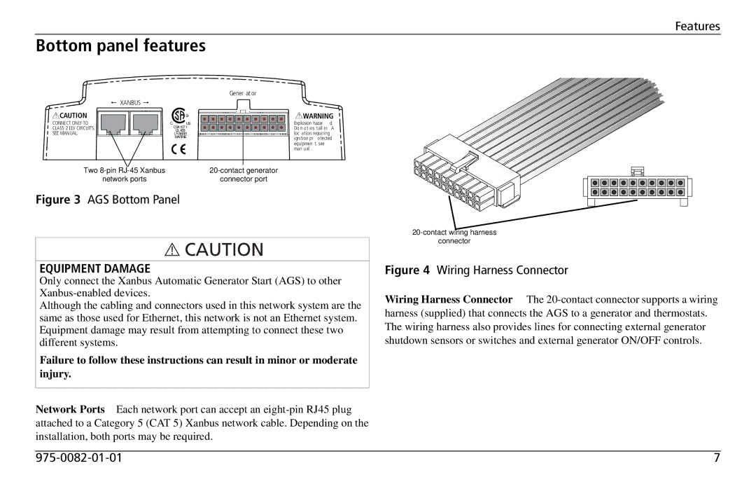
Figure 3 AGS Bottom Panel
EQUIPMENT DAMAGE
Only connect the Xanbus Automatic Generator Start (AGS) to other
Although the cabling and connectors used in this network system are the same as those used for Ethernet, this network is not an Ethernet system. Equipment damage may result from attempting to connect these two different systems.
Failure to follow these instructions can result in minor or moderate injury.
Network Ports Each network port can accept an
connector
Figure 4 Wiring Harness Connector
Wiring Harness Connector The
7 |