Installation and Configuration
Front Panel
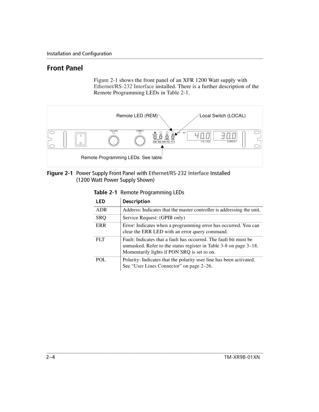
Figure 2-1 shows the front panel of an XFR 1200 Watt supply with Ethernet/RS-232 Interface installed. There is a further description of the Remote Programming LEDs in Table 2-1.
Remote LED (REM) | Local Switch (LOCAL) |
Remote Programming LEDs. See table.
Figure 2-1 Power Supply Front Panel with Ethernet/RS-232 Interface Installed (1200 Watt Power Supply Shown)
Table 2-1 Remote Programming LEDs
|
|
ADRLED | DescriptionAddress: Indicates that the master controller is addressing the unit. |
|
|
SRQ | Service Request: (GPIB only) |
|
|
ERR | Error: Indicates when a programming error has occurred. You can |
| clear the ERR LED with an error query command. |
|
|
FLT | Fault: Indicates that a fault has occurred. The fault bit must be |
| unmasked. Refer to the status register in Table |
| Momentarily lights if PON SRQ is set to on. |
|
|
POL | Polarity: Indicates that the polarity user line has been activated. |
| See “User Lines Connector” on page |
|
|
