Initial Inspection
Ethernet/RS-232 Interface Subplate and PCB
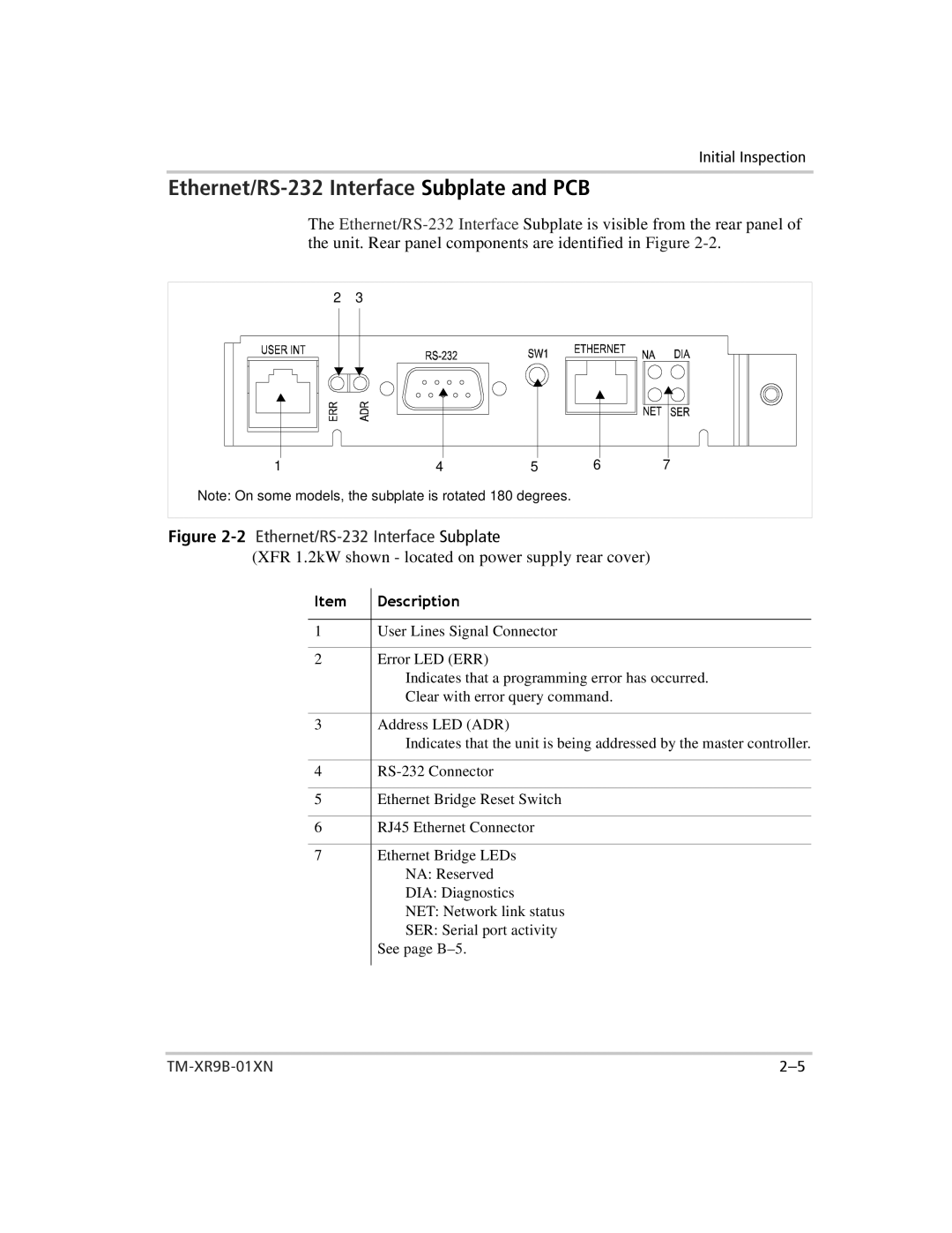
The
2 3
1 | 4 | 5 | 6 | 7 |
Note: On some models, the subplate is rotated 180 degrees.
Figure 2-2 Ethernet/RS-232 Interface Subplate
(XFR 1.2kW shown - located on power supply rear cover)
|
|
1Item | DescriptionUser Lines Signal Connector |
|
|
2 | Error LED (ERR) |
| Indicates that a programming error has occurred. |
| Clear with error query command. |
|
|
3 | Address LED (ADR) |
| Indicates that the unit is being addressed by the master controller. |
|
|
4 | |
|
|
5 | Ethernet Bridge Reset Switch |
|
|
6 | RJ45 Ethernet Connector |
|
|
7 | Ethernet Bridge LEDs |
| NA: Reserved |
| DIA: Diagnostics |
| NET: Network link status |
| SER: Serial port activity |
| See page |
|
|