Operation
Table
|
|
Command | Description |
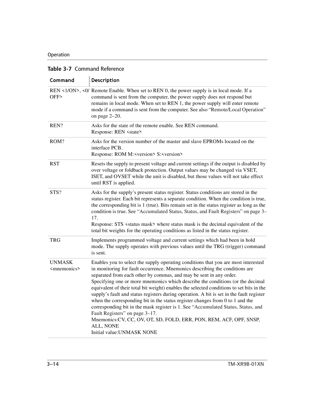
REN <1/ON>, <0/ R mote Enable. When set to REN 0, the power supply is in local mode. If a | |
OFF> | command is sent from the computer, the power supply does not respond but |
| remains in local mode. When set to REN 1, the power supply will enter remote |
| mode if a mmand is sent from the computer. See also “Remote/Local Operation” |
| on page |
REN? | Asks for he state of the remote enable. See REN command. |
| R ponse: REN <state> |
ROM? | Asks for he version number of the master and slave EPROMs located on the |
| interface PCB. |
| R ponse: ROM M:<version> S:<version> |
|
|
RST | R ets the supply to present voltage and current settings if the output is disabled by |
| over voltage or foldback protection. Output values may be changed via VSET, |
| ISET, and OVSET while the unit is disabled, but those values will not take effect |
| until RST is applied. |
|
|
STS? | Asks for he supply’s present status register. Status conditions are stored in the |
| status reg ster. Each bit represents a separate condition. When the condition is true, |
| the correspo ding bit is 1 (true). Bits remain set in the status register as long as the |
| condition is true. See “Accumulated Status, Status, and Fault Registers” on page 3– |
| 17. |
| Response: STS <status mask> where status mask is the decimal equivalent of the |
| total bit weights for the operating conditions as listed in the status register. |
|
|
TRG | Implements programmed voltage and current settings which had been in hold |
| mode. The supply operates with previous values until the TRG (trigger) command |
| is sent. |
|
|
UNMASK | Enables you to select the supply operating conditions that you are most interested |
<mnemonics> | in monitoring for fault occurrence. Mnemonics describing the conditions are |
| separated from each other by commas, and may be sent in any order. |
| Specifying one or more mnemonics which describe the conditions (or the decimal |
| equivalent of their total bit weight) enables the selected conditions to set bits in the |
| supply’s fault and status registers during operation. A bit is set in the fault register |
| when the corresponding bit in the status register changes from 0 to 1 and the |
| corresponding bit in the mask register is 1. See “Accumulated Status, Status, and |
| Fault Registers” on page |
Mnemonics:CV, CC, OV, OT, SD, FOLD, ERR, PON, REM, ACF, OPF, SNSP,
ALL, NONE
Initial value:UNMASK NONE