Installation and Configuration
User Lines
User Lines
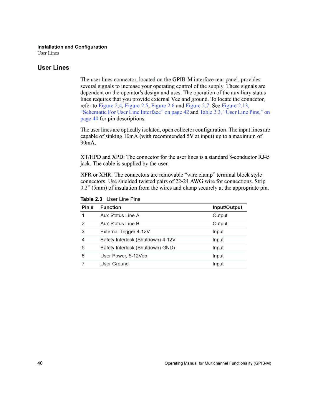
The user lines connector, located on the
The user lines are optically isolated, open collector configuration. The input lines are capable of sinking 10mA (with recommended 5V at input) up to a maximum of 90mA.
XT/HPD and XPD: The connector for the user lines is a standard
XFR or XHR: The connectors are removable “wire clamp” terminal block style connectors. Use shielded twisted pairs of
Table 2.3 User Line Pins
Pin # | Function | Input/Output |
1 | Aux Status Line A | Output |
|
|
|
2 | Aux Status Line B | Output |
|
|
|
3 | External Trigger | Input |
|
|
|
4 | Safety Interlock (Shutdown) | Input |
|
|
|
5 | Safety Interlock (Shutdown) GND) | Input |
|
|
|
6 | User Power, | Input |
|
|
|
7 | User Ground | Input |
|
|
|
40 | Operating Manual for Multichannel Functionality |
